 |
|||
|
|
|||
|
Page Title:
Section IV. Maintenance Procedures |
|
||
| ||||||||||
|
|
 TM 11-6625-2884-30/NAVAIR 16-35TS3615-2
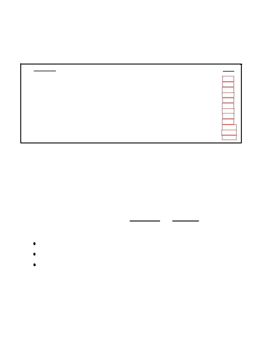
SECTION
IV
MAINTENANCE
PROCEDURES
CONTENTS
PAGE
GENERAL . . . . . . . . . . . ..................... . . . . . . . . . . ... . .......
CORRECTIVE ACTION . . . .. . . . . . . . . . . . .... . . . . . . . . ............
LAMP REPLACEMENT . . . . . ............................................
ASSEMBLY REMOVAL AND REPLACEMENT . . . . ..............................
ADJUSTMENT OF +5V POWER SUPPLY 1A3/1A4 PSI . . . . . . . . . . . . . . . . . . . . . . .
ADJUSTMENT OF +15V POWER SUPPLY 1A3/1A4 PS2 . . . . . . . . . . . . . . . . . . . . . . .
ADJUSTMENT OF -65V POWER SUPPLY 1A3/1A4 PS3 . . . . . . . . . . . . . . . . . . . . . . .
ADJUSTMENT OF +12V POWER SUPPLY 1A2 PS1 . . . . . .............................. .
REPLACEMENT OF POWER SUPPLIES . . . . .. . . . . . ...............................
REPLACEMENT OF PRINTED CIRCUIT BOARDS . . . . ................................ . . . . .
REPLACEMENT OF CONTROL INDICATOR 1A1A1 . . . . . . . . . . . . . . . . . . . . . . . . . . . .
CABLE REPAIRS . . . . ........................................... .
..
GENERAL
removal, and replacement actions listed in section III and in the Maintenance
Allocation Chart. These instructions include illustrations showing parts
locations. The section describes how to remove Control Panel Assembly 1A1.
Status Panel Assembly 1A2 and the two RF Modulation Assemblies 1A3 and 1A4 from
the BTS case. In addition, the section discusses replacement of the two printed
circuit cards of the BTS which are located in an enclosure on RF Modulation
Assemblies 1A3/1A4.
Instructions are provided for removal, replacement and adjustment of the
internal power supplies in the BTS.
Three of the power supplies are located in Control Panel Assembly 1A1.
+5V Power Supply PS1.
+15V Power Supply PS2.
+1OV Power Supply PS3.
3-72
|
|
Privacy Statement - Press Release - Copyright Information. - Contact Us |
