 |
|||
|
|
|||
|
Page Title:
ADJUSTMENT OF +5 V POWER SUPPLY 1A3/1 A4 PS1 |
|
||
| ||||||||||
|
|
 TM 11-6625-2884-30/NAVAIR 16-35TS3615-2
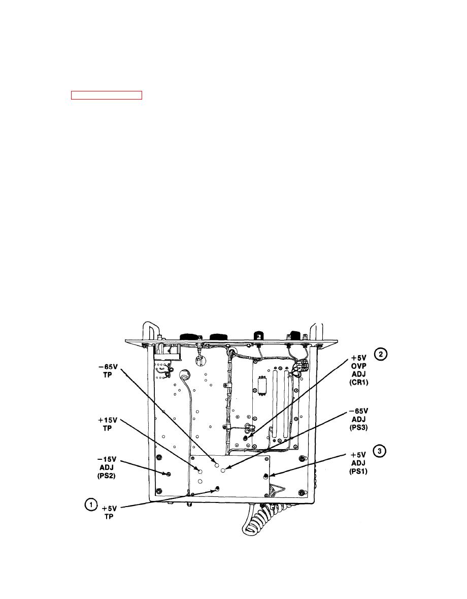
ADJUSTMENT OF +5 V POWER SUPPLY 1A3/1 A4 PS1
To adjust +5 V Power Supply 1A3/1A4 PS1, perform the following:
Remove RF modulation assembly from bench test set in accordance with
a.
bench. Connect power cord to an energized 115 V ac 60 Hz source.
b.
Check that front pane? POWER lamp illuminates.
If lamp does not light, check that front
panel circuit breaker on the RF modulation
assembly has not been tripped.
c. Connect the V lead of the DMM to the +5 V test point (1) and the COM
lead to chassis ground.
d.
Adjust CR1 (2) control fully clockwise.
e. Using screwdriver, rotate the PS1 +5 V ADJ control (3) until DMM indicates
+5.0 v.
f.
Adjust CR1 control (2) counterclockwise while observing DMM. When DMM
reading drops to less than 2 volts, stop adjustment.
Adjust CR1 control (2) 1/2 turn clockwise.
3-81
|
|
Privacy Statement - Press Release - Copyright Information. - Contact Us |
