 |
|||
|
|
|||
|
Page Title:
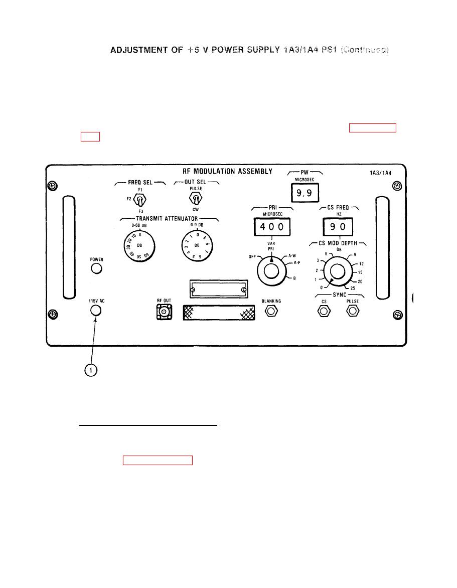
ADJUSTMENT OF +5 V POWER SUPPLY 1A3/1 A4 PS1 (cont) |
|
||
| ||||||||||
|
|
 TM 11-6625-2884-30/NAVAIR 16-35TS3615-2
h.
Pull and set POWER circuit breaker (1).
i.
Observe
DMM
for
a
+5
V
reading.
Remove test leads from RF modulation assembly.
j=
k.
Replace RF modulation assembly in BTS using the procedure in paragraph
ADJUSTMENT OF +15 V POWER SUPPLY 1A3/1A4 PS2
+15 V Power Supply 1A3/1A4 PS2.
To adjust +15 V Power Supply 1A3/1A4 PS2
a.
perform the following:
(1) Remove RF modulation assembly from bench test set in accordance
with paragraph 3-32a. Set RF modulation assembly upside down on the
test bench. Connect the power cord to an energized 115 V ac, 60 Hz.
source.
(2) Check that front panel power lamp DS1 illuminates,
|
|
Privacy Statement - Press Release - Copyright Information. - Contact Us |
