 |
|||
|
|
|||
|
Page Title:
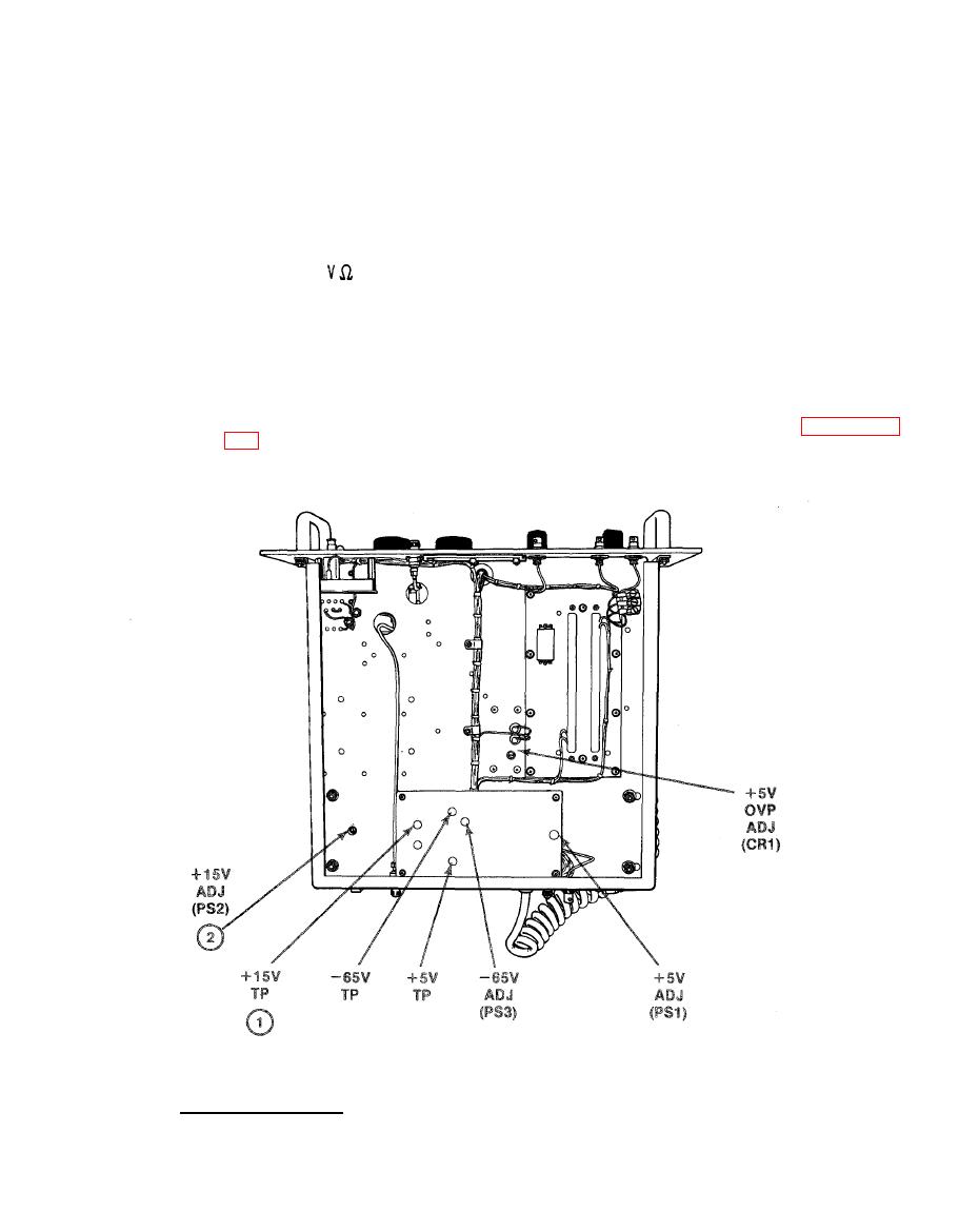
ADJUSTMENT OF +5 V POWER SUPPLY 1A3/1 A4 PS1 (cont) |
|
||
| ||||||||||
|
|
 TM 11-6625-2884-30/NAVAIR 16-35TS3615-2
N
O
T
E
If lamp does not light, check that
front panel circuit breaker on the
RF modulation assembly has not been
tripped.
(3) Connect the
lead of the DMM to the +15 V test point (1) and DMM
common lead to the chassis ground.
(4) Using screwdriver, rotate the PS2 +15 V ADJ control (2) clockwise or
counterclockwise until the DMM indicates +15.0 V.
(5) Remove test 1 cads from RF modulation assembly.
(6) Reinstall
RF modulation assembly in BTS using the procedure in paragraph
-15V Power Supply.
There is no adjustment to the -15 V Power Supply.
3-83
|
|
Privacy Statement - Press Release - Copyright Information. - Contact Us |
