
TM 5-6625-2691-13&P
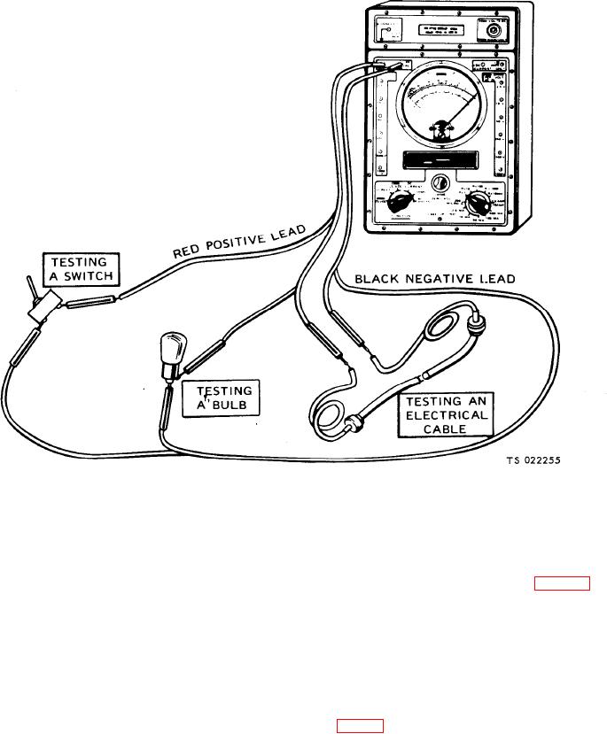
Figure 7-5. TS-352 continuity test.
(4) Look at the meter needle.
shorts, do the following steps:
(a) If the needle swings to the far right over the
(1) Set up and "zero" the multimeter (figs. 7-2,73
"0" on the top scale (on all three meters), the circuit
or 7-4).
has continuity.
CAUTION
(b) If the needle doesn't move, the circuit is open
Failure to do the following step can
(broken).
damage the multimeter.
(2) Disconnect the circuit being tested.
(c) If the needle jumps or flickers there is a loose
connection in the circuit being tested.
(3) With all three multimeters, connect one probe
c. Testing for Shorts. A short (or short circuit) occurs
to one circuit and the other probe to the other circuit or
when two circuits that should not be connected have
ground (if checking for a short to ground). The example
metal to metal contact with each other. A short also oc-
below (fig. 7-6) shows a check to see if wire "A" is
curs when a circuit that should not touch ground has
shorted to wire "B" in the wiring harness.
metal to metal contact with ground. To check for