
TM 5-6625-2691-13&P
Figure 7-6. Testing for shorts.
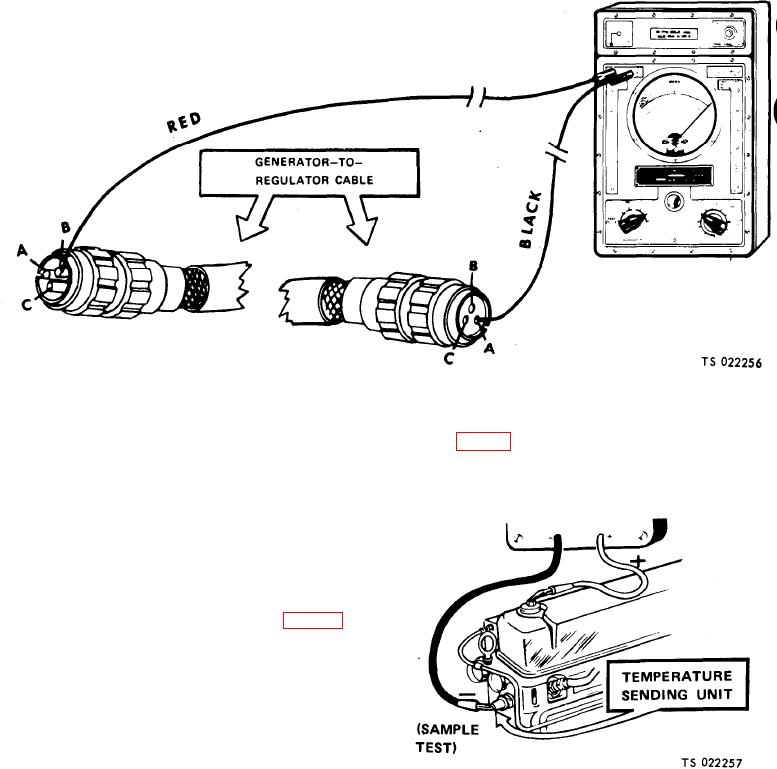
below (fig. 7-7) shows measuring the resistance of a
(4) Look at the needle.
temperature sending unit,
(a) If the needle swings to the far right over the
"0" on the top scale (on all three meters), the circuits
are shorted.
(b) If the needle doesn't move, the circuits are
not shorted.
(c) If the needle jumps or flickers, the circuits
are occasionally shorted.
d. Testing Resistance. To measure resistance in a cir-
cuit, do the following steps:
(1) Set up and "zero" the multimeter (figs. 7-2,7-3
or 7-4).
CAUTION
Failure to do the following step can
damage the multimeter.
(2) Disconnect the circuit being tested.
(3) If the test in this manual calls for an "ohms
range" different than" RXI" or " Xl", set the selector
switch to that range (such as" RX10" or" X10").
NOTE
"Zero" the meter whenever you change ranges.
(4) With all three multimeters, connect the probes
across the circuit or item to be measured. The example