 |
|||
|
|
|||
|
Page Title:
RF MODULATOR ASSEMBLY A3 AND SYNTHESIZER ASSEMBLY A4 REPLACEMENT. |
|
||
| ||||||||||
|
|
 TM 11-6625-2975-40
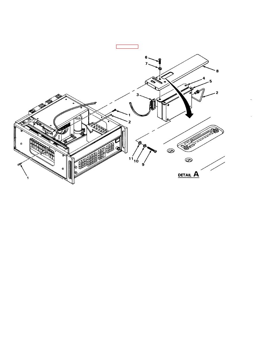
RF MODULATOR ASSEMBLY A3 AND SYNTHESIZER ASSEMBLY A4 REPLACEMENT.
MATERIALS/PARTS: Modulator, rf, assembly A3 (PN 629-9750-001)
Synthesizer assembly A4 (PN 629-9760-001)
PRELIMINARY PROCEDURE: Remove dust cover (para 2-28).
EL9LY040
REMOVAL
1. Remove two screws (1) from each side of chassis,
2. Unplug coaxial connector (2) and connector P5 (3) from assembly A3 (4).
3. Lift assemblies A3 (4) and A4 (5) from chassis as a unit.
NOTE
If assemblies A3 (4) and A4 (5) are to be separated, perform steps 4 and 5.
4.
Remove four screws (6) and Iockwashers (7) and remove top bracket (8).
Remove four screws (9), Iockwashers (10), and flat washers(11) and pull assemblies A3 (4)
5.
and A4 (5) apart.
|
|
Privacy Statement - Press Release - Copyright Information. - Contact Us |