
TM 5-6625-2691-13&P
Section IV. REMOVAL AND INSTALLATION OF MAJOR COMPONENTS AND
ASSEMBLIES
5-6. Doors
three hinged doors: two doors for ventilation and one
for the control panel. The housing is easily removable
Removal. Remove hinges and remove doors as re-
C.
quired.
for complete access to the interior for servicing.
b. Replacement. Replace a damaged or unserviceable
Latches are used to secure the door for storage and
door.
shipment.
c. Installation. Install by replacing hinges.
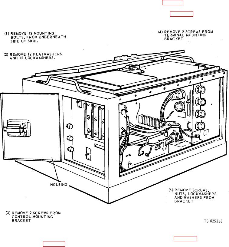
b. Removal. Refer to figure 5-2 and remove the hous-
ing.
5-7. Housing
a. Removal. The housing completely encloses all
components and controls. It is a one piece unit with
stall the housing.
Figure 5-2. Housing, removal and installation.
5-8. Wind Switch
b. Installation Refer to figure 5-3 and install the
a. Removal. Refer to figure 5-3 and remove the wind
wind switch.
switch.