TM 5-6350-264-14&P-12
NAVELEX EE 181-AA-OMI-120/E121 C-7359-60-1
TO 31S9-2FSS9-1-12
Table 5-1. Troubleshooting Procedures - Continued
Corrective action
Probable cause
Trouble
from A1-TP5 to Transmitter chas-
f. (cont)
1. (cont)
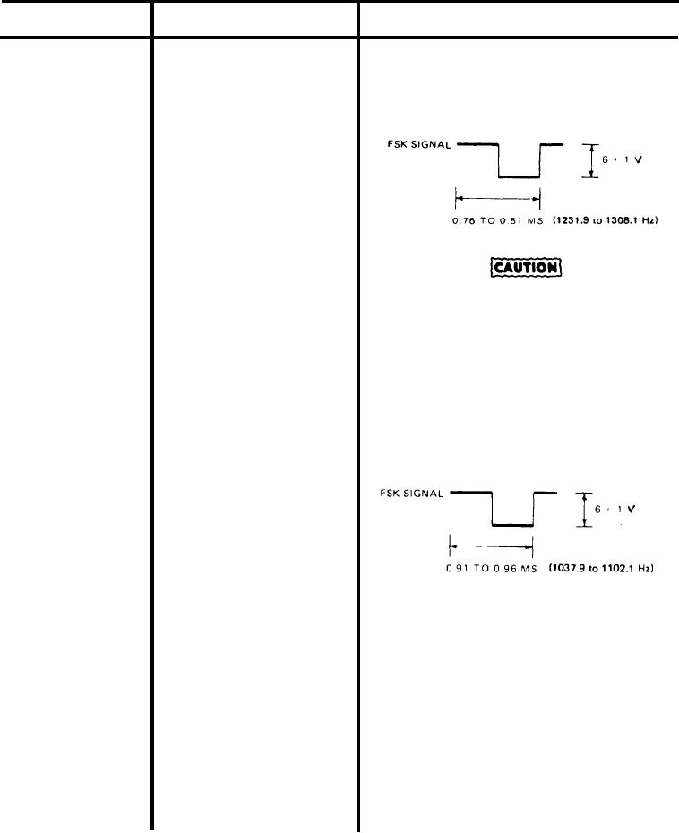
sis. The scope should display FSK
signal as a squarewave of 6 1 vdc,
and 0.81 to 0.76 ms (1231.9 to
1308.1 Hz).
Do NOT short A1-E14 to chassis/
ground or equipment will be
damaged.
f. Disconnect jumper from A1-TP5 and
chassis. Connect jumper to A1-E14 and
A1-TP5. The scope should display
FSK signal as a squarewave of
6 1 vdc, and 0.96 to 0.91 ms
(1037.9 to 1102.1 Hz).
g. If either of these FSK signals is in-
correct, replace Data Transmitter.
(1) To remove Data Transmitter, tag,
identify, and disconnect wires
from TB6 and TB7. Remove
screws that secure Data Trans-
mittter to standoffs in CU. Be
careful not to drop Transmitter
inside CU. Remove screws that
secure cover and remove cover.
Remove code plug from its soc-
ket on PC board A2.
5-14

