
TM 5-6350-264-14&P-12
NAVELEX EE 181-AA-OMI-120/E121 C-7359-60-1
TO 31S9-2FSS9-1-12
Table 5-1. Troubleshooting Procedures - Continued
Corrective action
Trouble
Probable cause
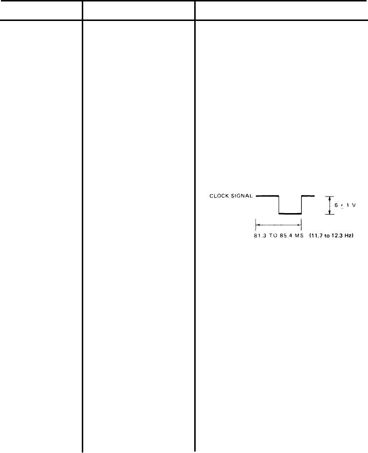
c. If meter indicates less than 0.6 vac,
f. (cont)
1. (cont)
use oscilloscope to check clock
signal on PC board A2. Remove
screws that secure Data Trans-
mitter cover and remove cover.
Set oscilloscope as follows:
volts/division
@2v
time/division
@10ms
input
@dc.
Connect scope probe to A2-TP2,
red. Connect scope ground to Trans-
mitter chassis. The scope should
display clock signal as a square-
wave of 6 1 vdc, and 85.4 to 81.3
ms (11.7 to 12.3 Hz).
d. If this indication is not correct, replace
Data Transmitter.
e. If clock signal is good use oscillo-
scope to check FSK signal on
PC board A1. Turn off switch S1
on power supply and remove screws
securing Data Transmitter to stand-
offs in CU. Carefully move Data
Transmitter so that test points on
PC board A1 can be reached. Turn
on switch S1. Set oscilloscope
as follows:
volts/division
@2v
time/division
@0.1ms
input
@dc.
Connect scope probe to A1-TP7
(violet) and scope ground to Trans-
mitter chassis. Ground A1-TP5,
green, by connecting a jumper
5-13