 |
|||
|
|
|||
|
|
|||
| ||||||||||
|
|
 TM
11-6625-467-34
(5) Lift up the connector plate (5) approxi-
response adjustment (para 3-21).
mately 3/4 inch and remove the connector.
NOTE
The tips on the card guides (14 and 15) fit
i n t o the receptacle connectors (4). Lift
straight up on connectors when removing
then..
h. 500-kHz fm oscillator deviation sensitivity ad-
justment (para 3-25).
b. Replacement.
(1) Connect any jumper wires that are required
adjustment (para 3-26).
on the connector plate (3).
(2) Lift up the connector plate approximately
inch and place the receptacle connector (4) on the
adjustment (para 3-27).
k. 5 0 0 - k H z b a n d p a s s f i l t e r a d j u s t m e n t ( p a r a
card guide (14 and 15) tips.
(3) Replace the 15 machine screws (12) and the
15 lockwashers (13) in the connector plate (3).
(4) Solder the wires to the terminals on the
connector plate (3).
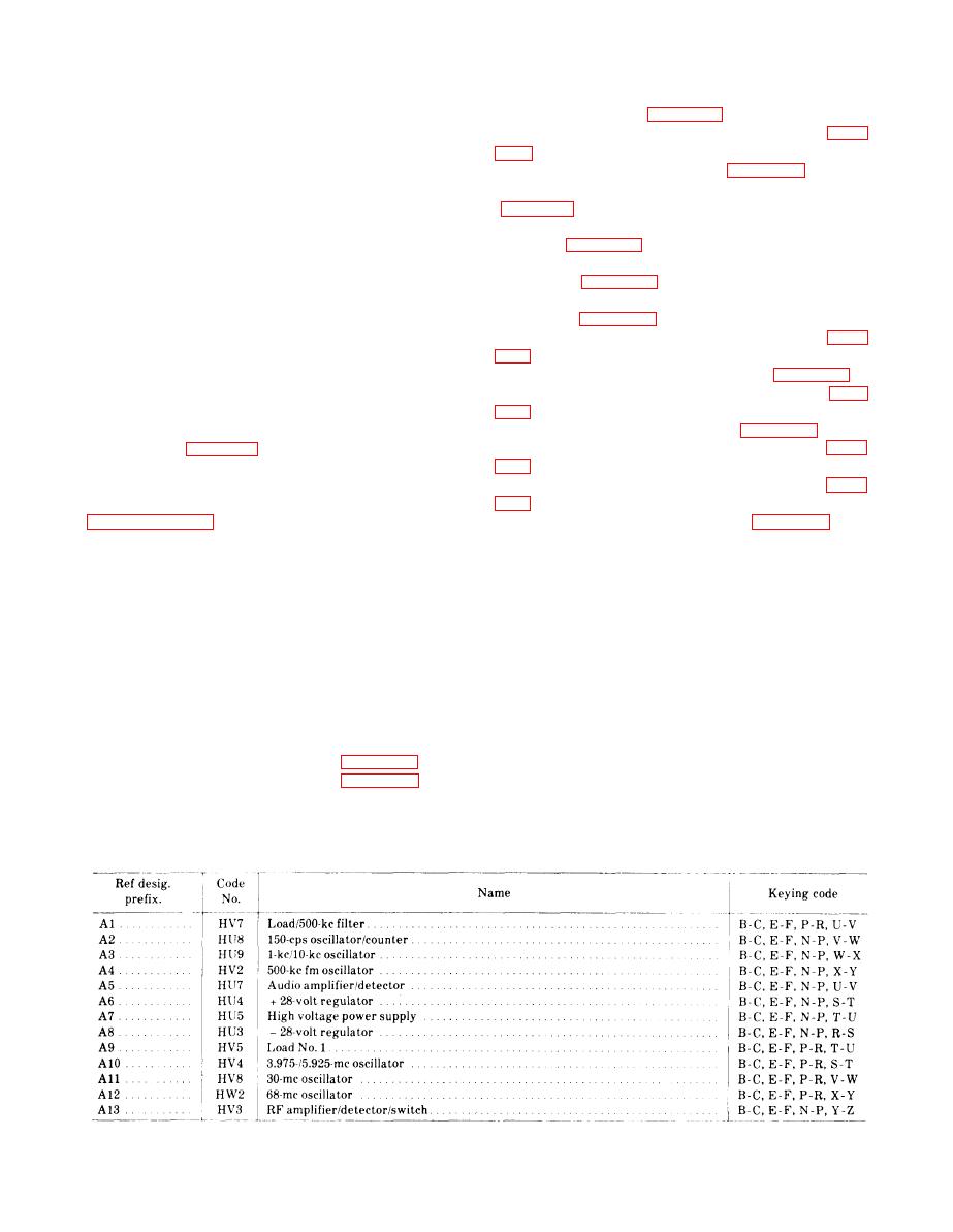
(5) Replace the keys in the new connector. The
chart below (table 3-4) shows the keying code for
each circuit card connector.
3-17. General Adjustment Procedures
procedures for the various functional circuits in the
t e s t set. Always perform the adjustment pro-
3-18. +28-Volt Regulator Adjustment
cedures for a circuit after a repair operation. The
Perform the following procedures to adjust the
adjustment procedures can also be used in trouble-
+28-volt regulator:
shooting the test set by attempting to adjust a cir-
a. Remove the test set from the case.
cuit that is suspected to be faulty. If the circuit can-
b. Using the module extender board, extend
not be adjusted, the fault is probably in that circuit.
+28-volt regulator circuit card HU4 above the card
When a complete alignment of the test set is neces-
cage.
s a r y , perform the adjustment procedures in the
c. Connect power to the equipment and set the
o r d e r of their appearance. The adjustment pro-
POWER switch to ON.
cedures and paragraph references are listed in a
d. Pull the shaft of interlock switch S12 to the
through q below.
override position.
e. S e t t h e P O W E R S E L E C T O R s w i t c h t o
NORMAL.
c. Audio amplifier/detector gain adjustment
f. Connect the ME-202/U between J3 (+) and J5
TABLE 3-4, Circuit Card Connector Keying Code
3-43
|
|
Privacy Statement - Press Release - Copyright Information. - Contact Us |