 |
|||
|
|
|||
|
Page Title:
RF OUTPUT CONNECTOR A6J5 REPLACEMENT. |
|
||
| ||||||||||
|
|
 TM 11-6625-2975
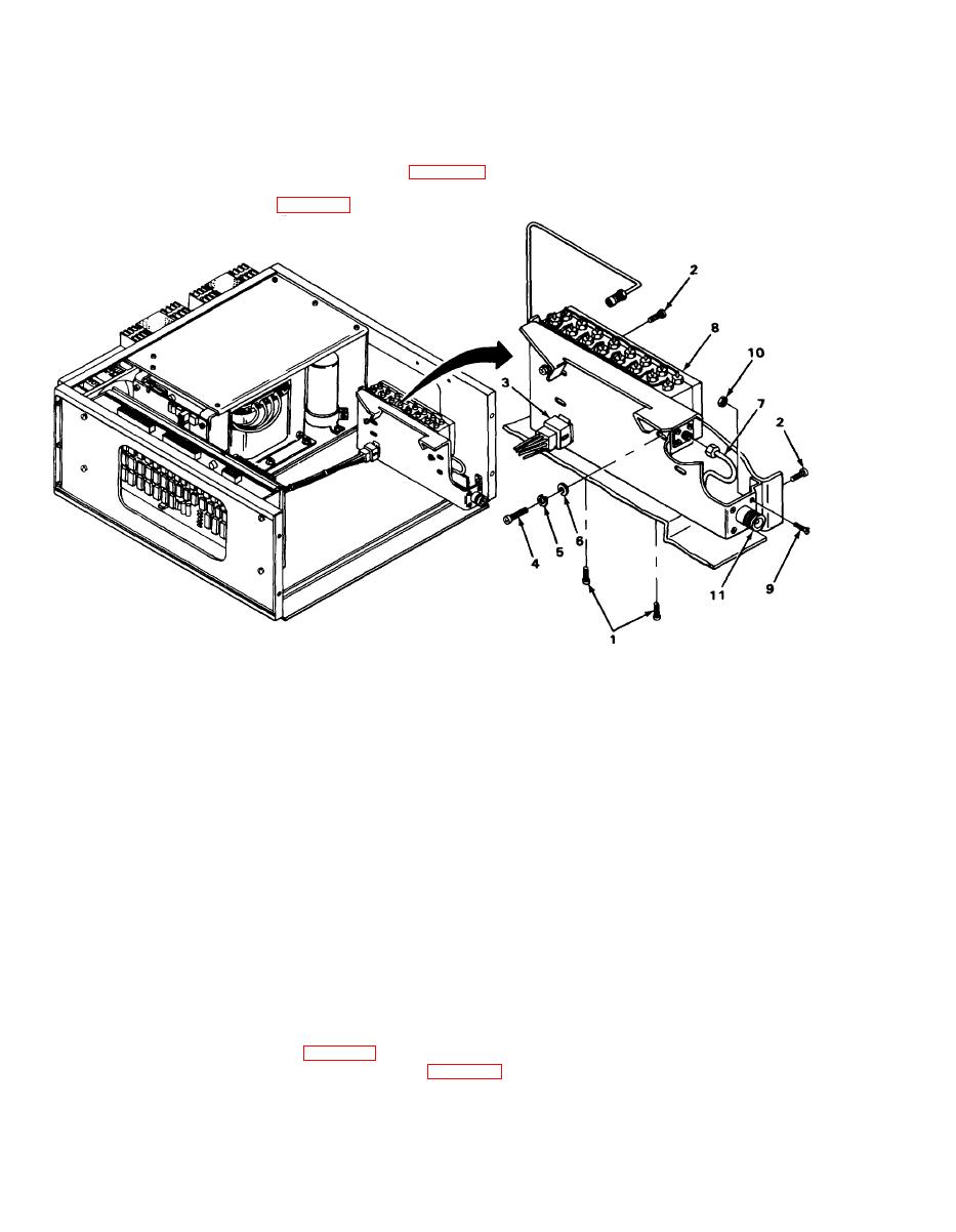
RF OUTPUT CONNECTOR A6J5 REPLACEMENT.
MATERIALS/PARTS: Connector, jack, A6J5(PN KN19-154M06)
PRELIMINARY PROCEDURE: Remove front paneI (para 2-29).
Remove rf modulator assembly A3 and synthesizer assembly A4
EL9LY045
REMOVAL
1. Remove two screws (1) from bottom of chassis and two screws (2) from side of chassis and
move A6AT1 bracket (3) to side.
2. Remove two screws (4), Iockwashers (5), and fiat washers (6).
3. Disconnect rf cable (7) from A6AT1 assembly (8).
4. Remove four screws (9) and locknuts (10) and remove rf connector (11).
INSTALLATION
1. Position rf connector (11) on A6AT1 bracket (3) and install four screws (9) and locknuts (10).
2. Connect rf cable (7) to A6AT1 assembly (8).
3. Position A6AT1 assembly (8) on A6AT1 bracket (3) and install two screws (4), Iockwashers
(5), and fiat washers (6).
4. Position A6AT1 bracket (3) in chassis and install two screws (2) through side of chassis and two
screws (1) through bottom of chassis.
FOLLOW-ON MAINTENANCE: install rf modulator assembly A3 and synthesizer assembly A4
Install front panel (para 2-29).
|
|
Privacy Statement - Press Release - Copyright Information. - Contact Us |
