 |
|||
|
|
|||
|
Page Title:
Control-interface Unit Troubleshooting |
|
||
| ||||||||||
|
|
 TM 11-6625-2937-13
5-7.
Control-interface Unit Troubleshooting
Test equipment
Common name
a. Tools and Test Equipment Required. The
Oscilloscope AN/USM-281C
following tools and test equipment are required for
Test Set, Electronic Systems AN/UYM-7
Digital tester
troubleshooting the control-interface unit.
Tool Kit, Electronic Equipment TK-IOSG
Tool kit
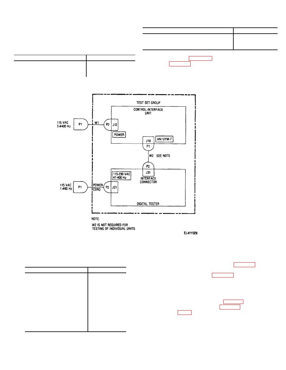
b. Test Setup. The control-interface unit test
Test equipment
Common name
setup is shown in figure 5-1. Perform the physical tests
given in table 5-3 prior to connecting the equipment in
Program card SM-A-942909-2
BITE card
the test setup.
Extender card SM-D-942431-2
STE extender card
Multimeter AN/USM-223
Figure 5-1. Control-interface unit, test setup.
c. Preliminary Control Settings. Set the
d. Testing Procedures.
The first step in
equipment controls as follows prior to functionally testing
troubleshooting the control-interface unit is to perform
the control interface unit.
the functional test procedure given in table 5-1. Then,
when a faulty indication is obtained, locate the
Control
Setting
appropriate MALUN ON in table 5-2 and continue as
Control-interface unit:
directed by the TEST or INSPECTION and
POWET ON/OFF
OFF
CORRECTIVE action columns of the table.
Power circuit breaker CB1
In (on)
e. Troubleshooting Procedures. Table 5-2
MODE SELECT
POWER OFF
contains the control-interface unit troubleshooting
Digital tester:
procedure. If the performance test (table 5-1) fails, refer
POWER
Down (off)
to the appropriate malfunction in table 5-2. Waveforrns
UUT POWER
Down (off)
are shown in figure
DISPLAY
PASS/FAIL
TEST RATE PER SEC
2M
NUMBER OF TESTS
20M
PROBE THRESHOLD
2V
5-2
|
|
Privacy Statement - Press Release - Copyright Information. - Contact Us |