 |
|||
|
|
|||
|
Page Title:
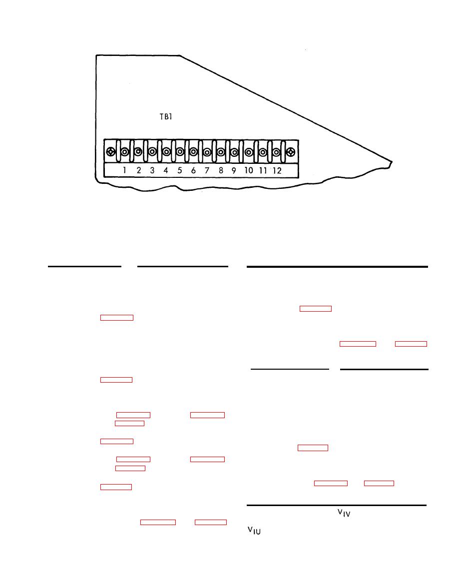
Figure 5-7. Terminal Board TB1 Terminal Layout |
|
||
| ||||||||||
|
|
 TM 94931-378-13&P
AR 918991
J4 Pin
S9 Position
J4 Pin
S9 Position
XA2 Pin
S9 Position
S9 Position
XA2 Pin
47
DTR
CLK
47
CLK
93
DR
77
DR
47
ANLG IN
45
83
DTR
DATA
88
DATA
47
AN LG OUT
45
(16)
Move DVM negative lead from TPI (20,
Move DVM negative lead from TP5 (16,
(7)
(17)
Set OUTPUT SEL 1 switch S9 (21) to
each of the following positions and read
Read continuity to TP4 (17) with OUT-
(8)
PUT SEL 1 switch S9 (21) set in each of
continuity to the designated card con-
nector pins (figure 5-8). (See table 5-4,
the following positions: D T R , D R ,
13.)
DATA, CLK, ANLG IN, ANLG OUT and
ATS.
XA2 Pin
S9 Position
S9 Position
Pin
Move DVM negative lead from TP2 (19,
{9)
DTR
86
CLK
XA2-92
figure 2-1) to TPI (20).
DR
78
ATS
XA3-65
Set OUTPUT SEL 1 switch S9 (21) to
(10)
DATA
82
REF OSC.
Read continuity at terminal board TB1
(11)
TS MON Switch S11 Wiring Check. Check switch
9.
(77, figure 6-4), terminal 5 (figure 5-7).
S11 and associated wiring by performing the fol-
(See table 5-4, 14.)
lowing procedure:
Move DVM negative lead from TPI (20,
(12)
(1) Connect DVM negative lead to TP9 (50,
figure 2-1 ).
(13)
Read continuity at terminal board TB1
(2) Set TS MON switch S11 (52) to each of
(77, figure 6-4), terminal 6 (figure 5-7).
the following positions and read con-
(See table 5-4, 14.)
tinuity to the designated card connector
Move DVM negative lead from TP2 (19,
(14)
pins (figure 5-8). (See table 5-4, 15.)
figure 2-1 ) to TPI (20).
(15)
Set OUTPUT SEL 1 switch S9 (21) to
XA3 Pin S11 Position
XA3 Pin
S11 Position
each of the following positions and read
+10V
15
18
continuity to the designated card con-
-10V
40
RDR ALT
16
nector pins (figure 5-8). (See table 5-4,
REFOSC
17
22
14. )
|
|
Privacy Statement - Press Release - Copyright Information. - Contact Us |
