 |
|||
|
|
|||
|
|
|||
| ||||||||||
|
|
 TM 9-4931-378-13&P
Section V. TROUBLESHOOTING
through W5 and the power cable adapter shall be per-
a. This section contains procedures for Iocating and
formed.
correcting operating troubles which may develop in the
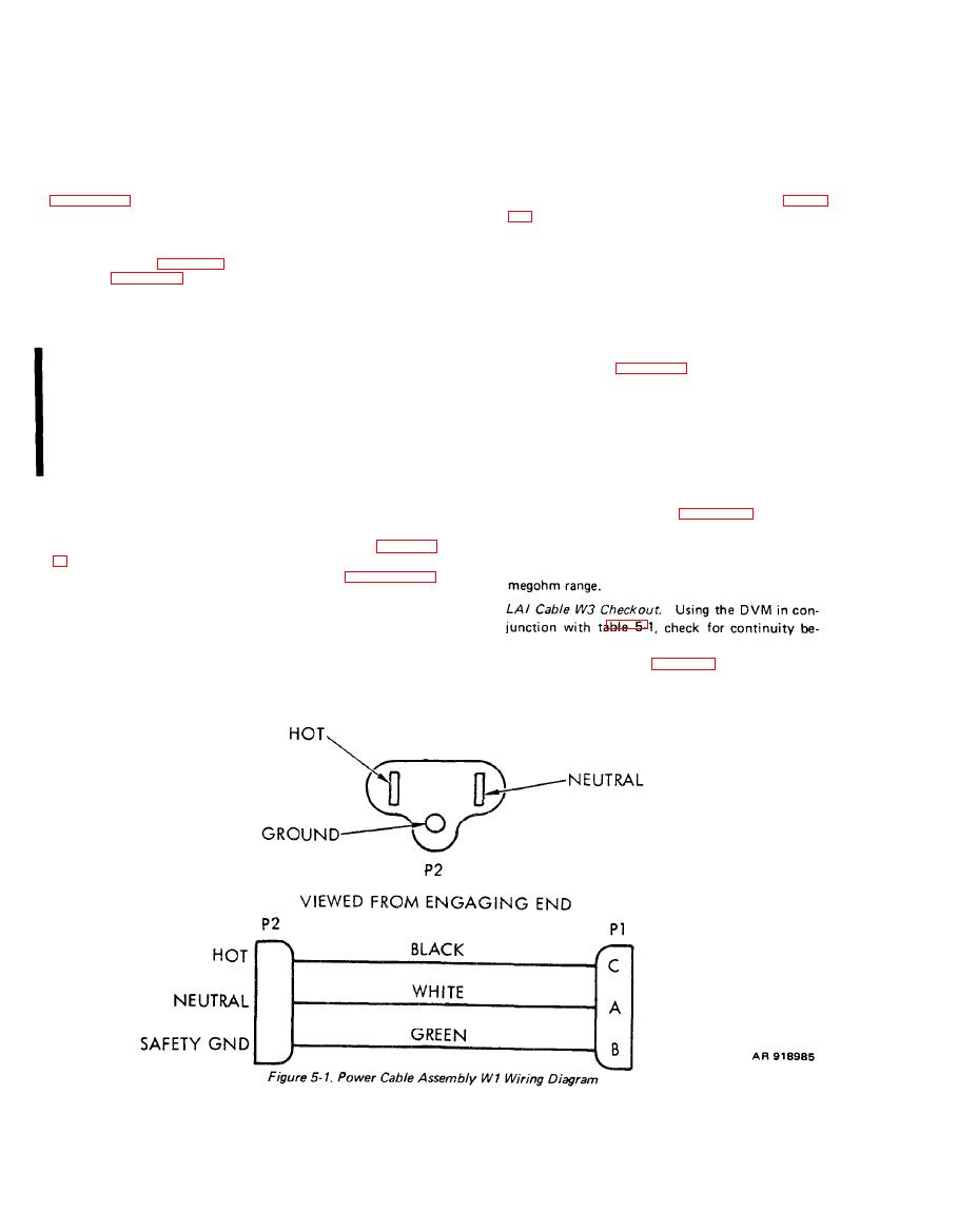
a. AC Power Cable W1 Checkout. Using the DVM
test set. The procedures are presented in a logical order.
set to read resistance in conjunction with figure
Performing the checkout as presented WiII assure you
that the test set is operational Each malfunction of a
tween interconnected connector pins. Unless
shop replaceable unit (SRU) or component is related to
otherwise noted, the resistance to all other pins or
actions listed in table 5-4 which will help you correct the
to the connector shells should be in the megohm
problem. Table 5-4 lists malfunctions in checkout order.
range. Flexing the cabie while making resistance
You should perform the checkout in the order of
checks will aid in isolating intermittent connec-
presentation. When you have performed a corrective
action, repeat the checkout procedure which Indicated
tions.
the trouble before you continue with the checkout.
b.
DC Power Cable W2 Checkout. Using the DVM in
b. The failure isolation shop set (FISS) electronic
conjunction with figure 5-2, check for continuity
circuit board: Air Data Subsystem provides slave boards
between interconnected connector pins. Unless
for use during troubleshooting to aid in the identification
otherwise noted, the resistance to all other pins or
of faulty circuit board assembles within the line replace-
able unit (LRU), once the faulty circuit board has been
to the connector shells should be in the megohm
identified, the slave board is returned to the shop set for
range. Flexing the cable while making resistance
future use and a replacement board is requisitioned for
checks will aid in isolating intermittent connec-
the LRU.
tions.
c. This manual lists the most likely malfunctions. If
Power Cable Adapter W6 Checkout. Using the
c.
a malfunction is not listed (except for obvious malfunc-
DVM in conjunction with figure 5-3, check for
tions and causes), or is not corrected by listed corrective
actions, notify the next higher level of maintenance.
continuity between interconnected connector
Disassembly and reassembly procedures are in Chapter
pins. Unless otherwise noted, the resistance to all
other pins or to the adapter shell should be in the
d. To assist you in troubleshooting, figure FO-1
shows the test set schematic.
d.
test set, a point-to-point continuity check of cables W1
tween interconnected connector pins. Connector
pin patterns are shown in figure 5-4. Unless other-
wise noted, the resistance to all other pins and to
the connector shells should be in the megohm
Change 1
|
|
Privacy Statement - Press Release - Copyright Information. - Contact Us |
