
TM 5-6625-2691-13&P
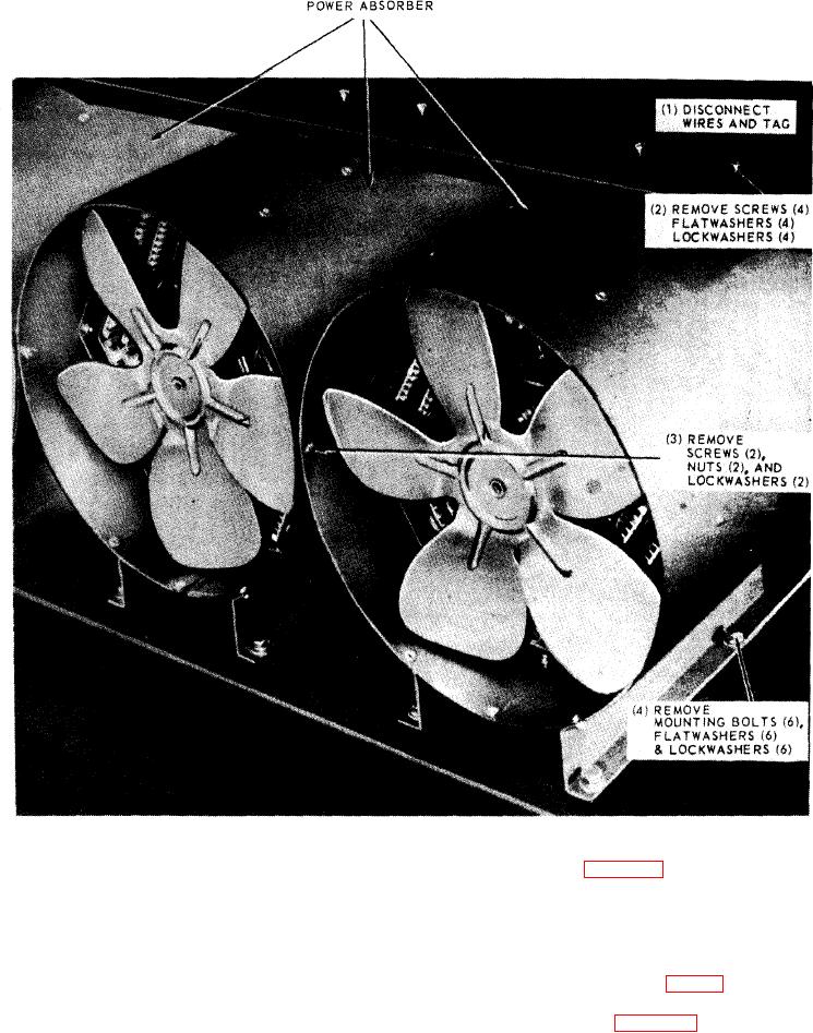
Figure 5-9. Power absorbers, removal and installation.
b. Removal. Refer to figure 5-9 to remove the power
flow stops. Thermal sensing switches are provided to
absorbers.
interrupt the load bus contractors in the event of over-
c. Cleaning and Inspection. Clean the power absor-
load. The power absorber consists of thirteen incremen-
bers with filtered compressed air. Inspect for cracks or
tal resistive load elements inclosed in a cylindrical
other damage. Replace if inspection proves the unit
duct, and totaling eleven KW. Each load element con-
faulty.
sists of nichrome ribbon sandwiched between heat dis-
d. Test. With an OHM meter (para 7-2), check ele-
sipating, finned plates. The unit is individually forced
ments for continuity.
air cooled by an internally mounted fan and motor. The
e. Installation. Refer to figure 5-9 and install the
unit is protected by a wind switch and thermal switch.
power absorber.
5-10 Change 1