TM 5-6350-264-14&P-10
NAVELEX EE 181-AA-OMI-110/E121 C-9412
T.O. 31S9-2FSS9-1-10
CHAPTER 2
OPERATING INSTRUCTIONS
Section I. OPERATING PROCEDURES
protection of the secure area. The LATCH/NON-
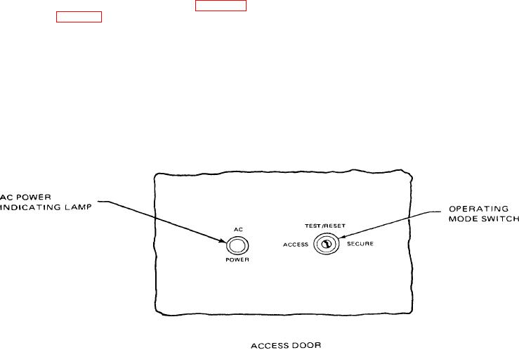
2-1. CONTROLS AND INDICATORS. The Control Unit
LATCH switch is normally placed in the LATCH
operator controls and indicators are shown in figure 2-1
position. When it is in the LATCH position, the
and described in table 2-1.
mode switch is turned to TEST/RESET and then
to either SECURE or ACCESS to clear an alarm
2-2. NORMAL OPERATING PROCEDURES.
condition. When the LATCH/NON-LATCH switch
is in the NON-LATCH position, the alarm
a.
Under normal conditions, the operating mode
condition may be cleared at the Monitor Cabinet.
switch (key operated) on the CU door is turned to
This switch is not accessible to the operator and
the ACCESS or SE-CURE position. The switch is
is set to one position or the other at the time of
turned to ACCESS to allow entry into the secure
installation.
area, and is turned to SECURE to allow
Figure 2-1. Control Unit Controls and Indicators
2-1

