 |
|||
|
|
|||
|
Page Title:
Expendable Supplies and Material |
|
||
| ||||||||||
|
|
 TM 11-6760-238-34
at direct support maintenance level. Refer to figure* FO-5
3-5. Operational Check
sheets 1 through 5 for a complete schematic diagram of
a. With power off and the shutter test set
the shutter test set Figure* FO-7 sheet through 4
separated from its case (para 3-8a) for access to its
comprise the wiring diagram for shut test set.
internal parts, examine the shutter test set for visual
signs of damage
Table 3-1. Test Equipment and Tools
b. Check for broken, burned or damaged wires
and insulation.
c. Examine the external connectors to ensure
Tool and test equipment
Used to
there are no bent or misaligned pins.
d. Ensure that all switches index properly and do
Voltmeter, ME-202B/U
Perform voltage
not bind.
measurements.
e. Check the fuses to ensure they are in good
Multimeter, AN/USM-223
Performs continuity
operating condition.
and assistance checks
f. Set all control switches to the off, neutral, or
Tool Kit, Photographic Repair
Perform repairs and
maximum counterclockwise positions.
TK-77/GF
alignment.
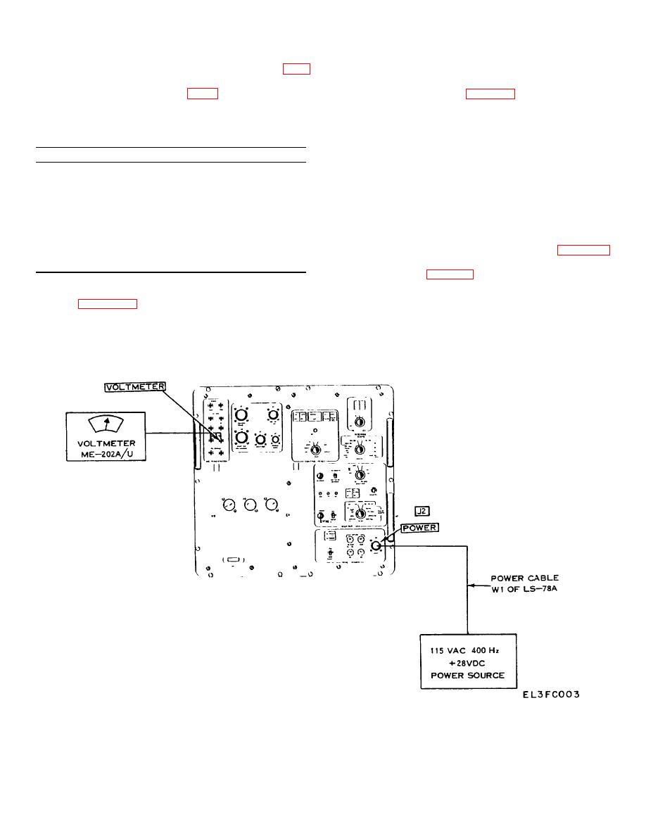
g. Connect test equipment as shown in figure 3-1
Tool Kit, Photographic Repair
Perform repairs and
and perform the steps of the following general
TK-77/GF
alignment.
operational check (table 3-2) in the order given to check
the shutter test set electrically.
3-4. Expendable Supplies and Material
CAUTION
Refer to appendix B for the list of expendable supplies
Observe polarity when connecting the
and materials.
ME-202B/U voltmeter cables to shutter
test set. All voltages displayed on the
voltmeter will be positive readings.
Figure 3-1. Operational check, test setup.
3-2
|
|
Privacy Statement - Press Release - Copyright Information. - Contact Us |