 |
|||
|
|
|||
|
Page Title:
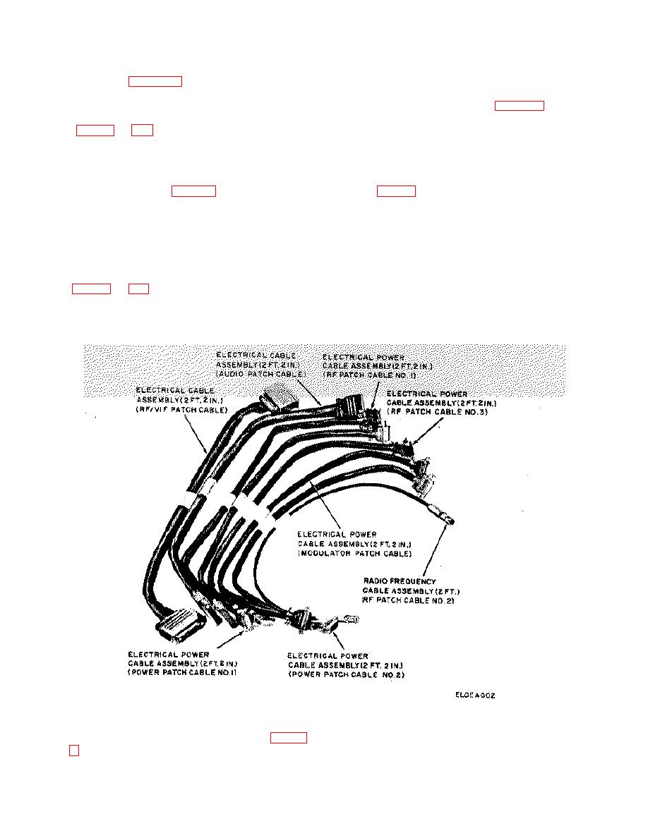
Figure 1-3. Cable Assembly Set, Electrical OA-2494/ARM-45. |
|
||
| ||||||||||
|
|
 TM 11-6625-409-12
AN/ARM-45(*) is furnished by an external 27.5-volt direct
power receptacle (not shown) i located on the rear of the
current (dc) source (para 1-15a).
remote control unit. The 614U-6 provides for the control.
and tuning o Transmitter 17L-7A and Receiver 51X-2B
when testing the AN/ARC-73 (para 2-9). Radio Set
1-11.
Description of Test Set Subassembly MX-
Control 614U-5 is used when testing the AN/ARC-73A.
3736/ ARM-45
Refer to TM 11-5821-217-12 for comparative
descriptions of the 614U-6 and 614U 5.
The MX-3736/ARM-45 contains the controls, jacks,
indicators, test cable receptacles, radio frequency (rf)
1-13. Description of Cable Assembly Set
dummy load, and cable assemblies required to perform
Electrical OA-2494/ ARM45
operational tests of the AN/ARC-73 or AN/ARC-73A.
The test cable receptacles (fig. 2-4) are located on a
The OA-2494/ARM-45 consists of eight cable., used for
shelf mounted inside the metal case. The receptacles
extending the electronic modules in Transmitter 17L-7A
are protected by hinged covers. The case of the MX-
and Receiver 51X-2B from their respective chassis when
3736/ARM-45 is equipped with carrying handles and a
troubleshooting the AN/ARC-73 and AN/ARC-73A. Five
removable hinged cover.
module extension cables are provided for use with the
17L-7A; three are provided for use with the 51X. 2B.
1-12. Description of Radio Set Controls 614U-6
and 614U-5
Radio Set Control 614U-6 (remote control unit) is located
on the front panel of the MX-3736/ARM-45 and is
secured by four mounting screws.
A control and
Figure 1-3. Cable Assembly Set, Electrical OA-2494/ARM-45.
22-conductor cable assembly that is used to connect the
1-14. Description of Test Cable Assemblies (fig. 1-
MX-3736/ARM-45 to either the 17L-7A or to the 17L-7A
section in Dual Shockmount
a. Cable No. 1. Cable No. 1 is a 7-foot 6-inch,
1-4
|
|
Privacy Statement - Press Release - Copyright Information. - Contact Us |