 |
|||
|
|
|||
|
Page Title:
AUDIO MODULATION GENERATOR OPERATION |
|
||
| ||||||||||
|
|
 TM 11-6625-2975-40
OPERATION.
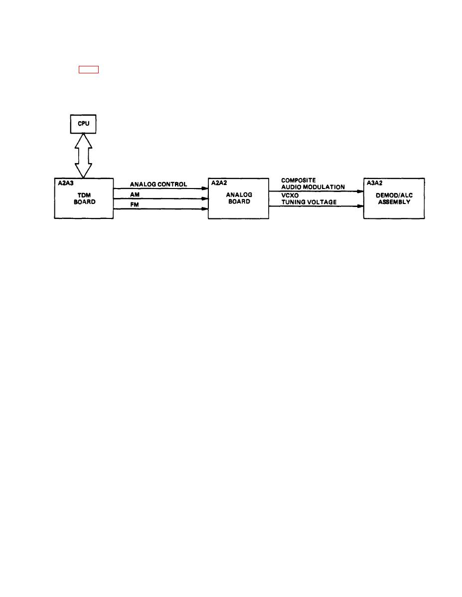
Refer to FO-2 and the following diagram while reading the text in this paragraph,
EL9LY008
The audio modulation generator, consisting of TOM board A2A3 and analog board A2A2, produces
audio signals used to modulate the selected rf carrier signal. The selected rf frequency (mode or
operation) controls the modulation requirements on the generator. When an rf carrier frequency is
selected, data from the CPU is supplied over the control bus to I/O port of TDM board A2A3. This data
is used to program the modulation generator to generate the correct audio signals. All audio modu-
Iation and analog control signals are generated on TDM board A2A3 and supplied to analog board
A2A2, Signals applied to the analog board are processed as described In the following modes.
VOR MODE
In VOR mode, A2A3 generates 1020-HZ audio tone, 30-Hz variable, 9960-Hz, and 9960-Hz FM (30-
Hz reference) signals that are supplied to analog board A2A2. Analog board A2A2 filters audio
modulation signals and combines all VOR signals to produce a composite VOR modulation signal. This
signal is supplied to demodulator/ale assembly A3A2, The phase relationship of the 30-Hz variable
and the 30-Hz reference signals determine the VOR radial.
Phase information relating to the 30-Hz variable and 30-Hz reference signals Is read back to the CPU
by TDM board A2A3 when requested by the CPU. This phase Information is transmitted to the CPU
through the control bus and is used to generate the VOR radial displayed on the front panel.
|
|
Privacy Statement - Press Release - Copyright Information. - Contact Us |