 |
|||
|
|
|||
|
Page Title:
FRONT PANEL ASSEMBLY A1 OPERATION. |
|
||
| ||||||||||
|
|
 TM 11-6625-2975-40
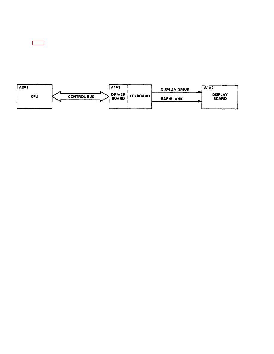
Refer to FO-2 and the following diagram while reading the text In this paragraph.
EL9LY007
Front panel assembly A1 A1 provides the operator with the means of communicating with test set. The
keyboard allows operator to select the required signals for testing, troubleshooting, alining, and/or
adjusting the unit under test. Digital displays and LED indicators on display board A1A2, plus Iighted
keys on A1 A1, provide operator with a readout of output signal parameters.
KEYBOARD DRIVER BOARD A1A1
Driver board A1 A1 contains I/O ports, keyboard, display driver circuits, bar/blanking circuits, and
key light driver circuits. Driver board A1A1 I/O ports are connected to the parallel control bus. All
Information is received and transmitted through the 1/0 ports through the control bus. When CPU
addresses I/O port and a write pulse is generated, data on the Input of the I/O port Is supplied to the
correct circuit In driver board A1 A1.
When cpu data at driver board A1A1 I/O port requests that a display be lit, this data gets latched In the
display driver circuits. The display driver circuits then generate display driver signals that are supplied
to display board A1A2, Iighting the correct display. If data at driver board A1A1 I/O port requests
either to bar or blank a digital display, data Is supplied to the bar/blank circuit. The bar/blank circult
produces correct bar or blank signals and supplies them to display board A1A2, which then bars or
blanks correct digital display. When data at the I/O port requests a specific key be lit, data Is latched
In the key light driver circuit. The Iight driver circuit then provides a lamp drive signal for Iighting the
correct lamp,
|
|
Privacy Statement - Press Release - Copyright Information. - Contact Us |
