 |
|||
|
|
|||
|
Page Title:
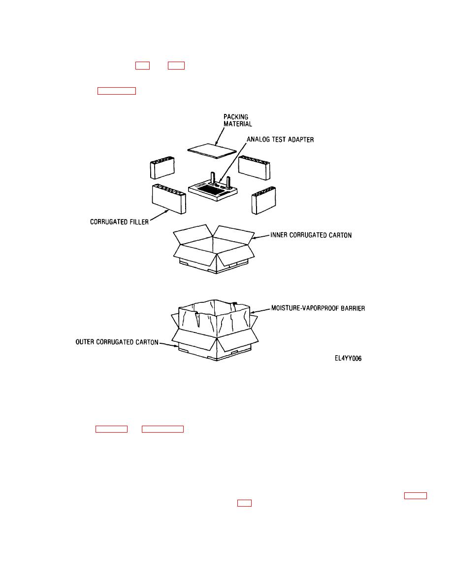
Figure 2-2. Analog test adapter typical packaging. |
|
||
| ||||||||||
|
|
 TM 11-6625-2937-13
b. Digital Tester. Refer to TM 11-6625-2951-
moisture-vapor-proof barrier.
(2) Remove corrugated filler and remove
13 for digital tester unpacking procedures.
c. Analog Test Adapter (fig. 2-2). When
inner carton.
(3) Open inner carton and remove packing
packaged for shipment or limited storage, the analog test
material from top and sides of analog test adapter.
adapter is placed in a double carton. A typical packaging
(4) Carefully remove analog test adapter
diagram is shown in figure 2-2. To unpack the analog
from carton.
test adapter proceed as follows:
(1) Open outer carton, and open
Figure 2-2. Analog test adapter typical packaging.
2-2.
Checking Unpacked Equipment
2-3.
Installation
Inspect and check the unpacked equipment as follows:
WARNING
a. Inspect the equipment for damage incurred
Be sure green wire from power cable is
connected to earth ground before
during shipment. If the equipment has been damaged,
report the damage on DD Form 6 (para 1-3b).
operating test group.
b. Check the equipment against the
The test set group will operate in environments kept
component listing in table 1-1 and appendix B to see if
reasonably dean to prevent contamination of switch and
the shipment is complete. Report all discrepancies in
circuit board contacts and maintained within a
accordance with the instructions of TM 38-750. The
temperature range of 41 to 131 F (5 to 55 C). The
equipment should be placed in service even though a
control-interface unit requires 115-volt ac, 400-Hz, 3-
minor assembly or a part that does not affect proper
phase primary input power, and the digital tester requires
functioning is missing.
115-volt ac, 400-Hz, single-phase power. The control-
c. Check to see whether the equipment has
interface unit, digital tester, analog test adapter and
been modified. (Equipment which has been modified will
extender boards require approximately a six-foot working
have the MWO number on the front panel, near the
space on a standard work bench for operation. To
nomenclature plate.) Check also to see whether all
interconnect the test set-group for testing, refer to figure
currently applicable MWO have been applied. (Current
MWO applicable to the equipment are listed in DA PAM
310-7.)
2-3
|
|
Privacy Statement - Press Release - Copyright Information. - Contact Us |