 |
|||
|
|
|||
|
Page Title:
Table 2-4. Preliminary Control Settings |
|
||
| ||||||||||
|
|
 TM 11-6825-2937-13
Table 2-3. Analog Test Adapter Controls and Monitor Points-Continued
Control, monitor point, or connector
Function
Blue
-12V/-15V
Black
GND
Yellow
+5V
Orange
+12V/+15V
Red
+28V
controls on control-interface unit and digital tester in
2-5.
Operation Under Usual Conditions
accordance with table 2-4.
a. Preliminary Starting Procedure.
Set
Table 2-4. Preliminary Control Settings
Component
Control
Setting
Control-interface unit
POWER ON/OFF switch
OFF position
MODE SELECT switch
POWER OFF position
Circuit breaker CB1
Reset (in) position
Digital tester
POWER switch
Down position (off)
UUT POWER switch
Down position (off)
DISPLAY switch
PASS/FAIL position
PROBE THRESHOLD switch
2V position
b. Visual Inspection. Trouble in the test set
proceed as follows:
(1) Set the digital tester controls as
group may be caused by abnormal conditions that may
follows:
easily be detected by a visual inspection. Visually
(a) POWER switch indicator in up
inspect the test set group as follows:
position (on) and observe indicator lights. POWER and
(1) Check that all cables and equipment
PROGRAM ERROR (red) indicators light.
are properly installed, complete, and undamaged.
(b) UTT POWER switch indicator up
(2) Check that all cables and equipment
are free of dirt, grease, or other foreign material that
position (on) and observe UT7 POWER indicator lights.
(c) Set TEST RATE PER SEC switch
could cause damage or interfere with proper operation of
the equipment.
in 2M position.
(3) Check all controls for proper, positive
(d) Set NUMBER OF TESTS switch
action.
in 20M position.
(4) Check circuit breaker on control-
(2) Set control-interface unit POWER
interface unit for reset position (in).
ON/OFF switch in ON position and observe POWER ON
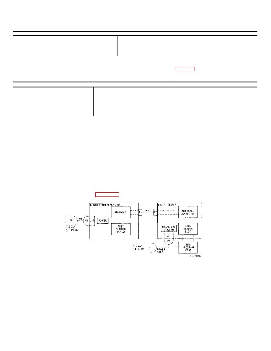
c. Control-interface Unit BITE Test. Connect
indicator lights.
the test set group in accordance with figure 2-6 and
Figure 2-6. Interconnections for control-interface unit BITE test.
(3) Perform BITE test as follows:
observe PROGRAM ENTER indicator lights.
(a) Insert BITE test program card in
(c) Observe that READY indicator
card reader slot of digital tester.
on digital tester lights after approximately 10 seconds
(b) Press PROGRAM
ENTER
and PROGRAM ENTER indicator goes of.
switch-indicator on digital tester to down position and
(d) Press either TEST switch-
indicator on digital
2-10
|
|
Privacy Statement - Press Release - Copyright Information. - Contact Us |
