 |
|||
|
|
|||
|
Page Title:
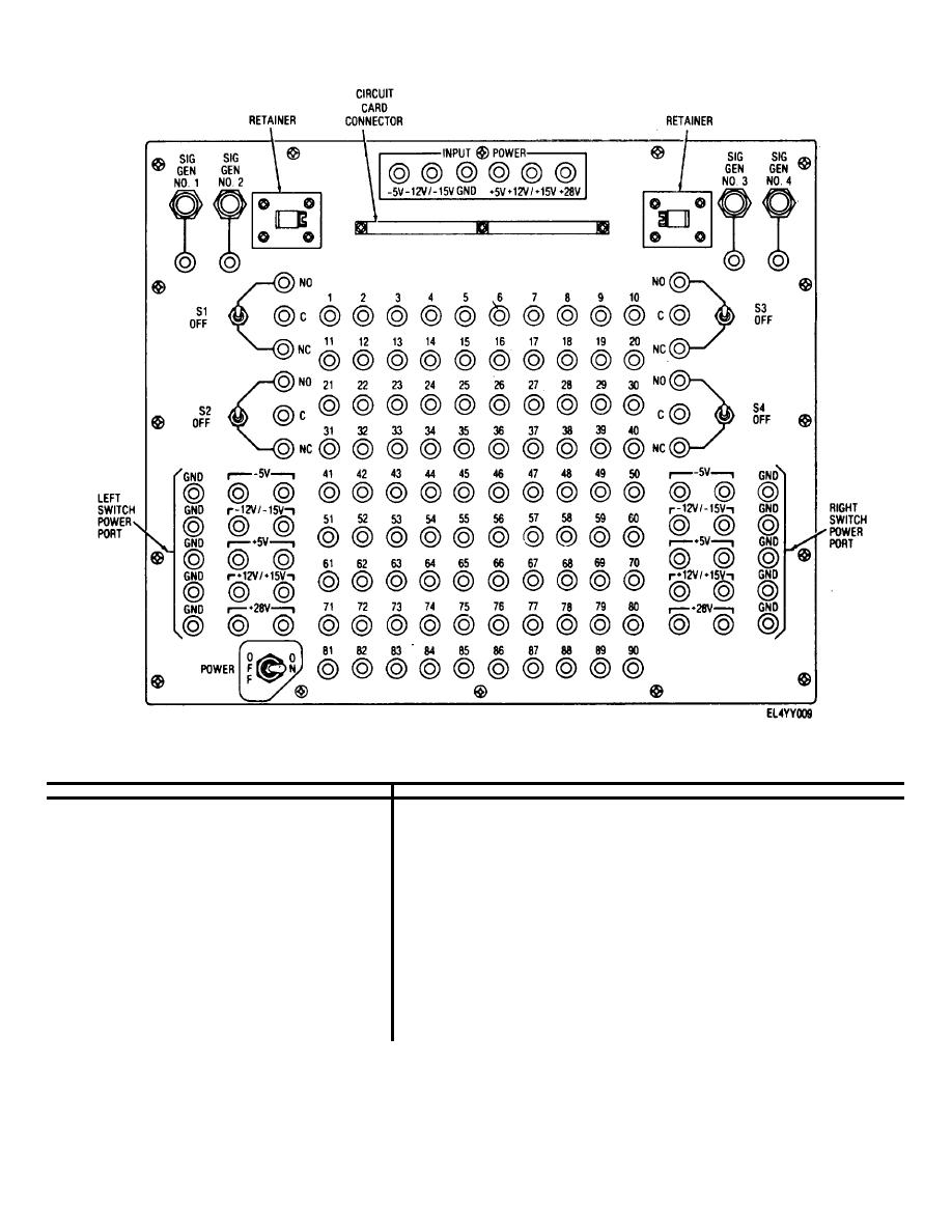
Figure 2-5. Analog test adapter, controls and monitor points |
|
||
| ||||||||||
|
|
 TM 11-6625-2937-13
Figure 2-5. Analog test adapter, controls and monitor points
Table 2-3. Analog Test Adapter, Controls and Monitor Points
Control, monitor point, or connector
Function
Right and left switch power port
Supplies necessary input voltages and grounds to test points 1 through 90, as applicable. The follow-
ing power port voltages are available in accordance with the particular external power supply or sup-
lies connected.
Green
-5V
Blue
-12V/-15V
Yellow
+5V
Orange
+12V/+15V
Red
+28V
Black
GND
Test points 1 through 90
Used for injecting voltage and signal inputs to particular portions of the analog circuit card under test.
POWER ON/OFF switch
In ON position, power is switched from the INPUT POWER CONNECTOR to the left and right switch
power ports
Switch S1 through S4
Two position switches that switch voltage or signal inputs to particular portions of analog card under
test
SIG GEN NO 1 through NO 4 connector
Provides interface to connect four signal generators to analog test adapter to perform analog circuit
card test.
Circuit card connector
Provides interface for connecting circuit card under test to the analog test adapter.
INPUT POWER connector jacks
As necessary, external power supplies are connected to these jacks at the following points:
Green
-5V
2-9
|
|
Privacy Statement - Press Release - Copyright Information. - Contact Us |
