 |
|||
|
|
|||
|
|
|||
| ||||||||||
|
|
 TM 11-6625-2885-30/NAVAIR 16-35TS3614-2
SECTION II
TROUBLESHOOTING
SECTION CONTENTS
PAGE
INTRODUCTION . . . . . . . . . . . . . . . . . . . . . . . . . . . . . . . . . . . . . . . . . . . . . . . . . . . . . . . . .
DEFINITIONS . . . . . . . . . . . . . . . . . . . . . . . . . . . . . . . . . . . . . . . . . . . . . . . . . . . . . . . . . . .
TEST CONDITIONS . . . . . . . . . . . . . . . . . . . . . . . . . . . . . . . . . . . . . . . . . . . . . . . . . . . . . . . .
TEST EQUIPMENT . . . . . . . . . . . . . . . . . . . . . . . . . . . . . . . . . . . . . . . . . . . . . . . . . . . . . . . .
EQUIPMENT SETUP . . . . . .. . . . . . . . . . . . . . . . . . . . . . . . . . . . . . . . . . . . . . . . . . . . . . . . . . .
FLTS STARTING PROCEDURE . . . . . . . . . . . . . . . . . . . . . . . . . . . . . . . . . . . . . . . . . . . . . .
BTS STARTING PROCEDURE . . . . . . . . . . . . . . . . . . . . . . . . . . . . . . . . . . . . . . . . . . . .. . . . . .....
POWER SUPPLIES AND LAMPS CHECK . . . . . . . . . . . . . . . . . . . . . . . . . . . . . . . . . . . . . . . . . . .
TEST LOGIC CHECK . . . . . . . . . . . . . . . . . . . . . . . . . . . . . . . . . . . . . . . . . . . . . . . . . . . . . .
RF OUTPUT LEVEL CHECK . . . . . . . . . . . . . . . . . . . . . . . . . . . . . . . . . . . . . . . . . . . . . . . . . . .
RF FREQUENCY CHECK . . . . . . . . . . . . . . . . . . . . . . . . . . . . . . . . . . . . . . . . . . . . . . . . . .
PRI AND CS CHECK . . . . . . . . . . . . . . . . . . . . . . . . . . . . . . . . . . . . . . . . . . . . . . . . . . . . . . . .
POWER SUPPLY TROUBLESHOOTING . . . . . . . . . . . . . . . . . . . . . . . . . . . . . . . . . . . . . . . . . . .
PRI TROUBLESHOOTING . . . . . . . . . . . . . . . . . . . . . . . . . . . . . . . . . . . . . . . . . . . . . . . . . . .
INTRODUCTION
3-4. Paragraph 3-8 gives the initial test setup. Troubleshooting information
is in paragraphs 3-11 through 3-20. Each paragraph gives the hookup and
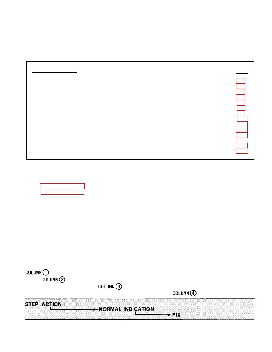
contains a test in chart form with four columns. The first column (1) numbers
the steps in ascending order. The second column (2) explains the test. The
third column (3) states what measurements should be observed for normal
operation. The fourth column (4) lists what course to follow if you don't get
the value stated in the third column. If "Normal Indication" still cannot be
obtained, a higher level maintenance is required. The foldout drawings at the
rear of this manual provide the details you need to trace circuits through
FLTS. References in parentheses are to paragraph numbers.
|
|
Privacy Statement - Press Release - Copyright Information. - Contact Us |