 |
|||
|
|
|||
|
Page Title:
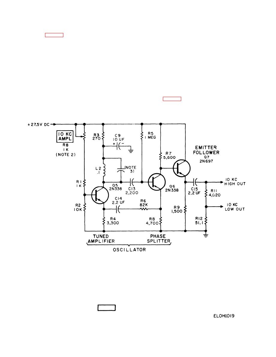
Figure 2-19. 10-kHz oscillator circuit, simplified schematic diagram |
|
||
| ||||||||||
|
|
 TM 11-6625-467-34
collector of Q5 and causes sustained circuit oscilla-
2-24. 10 kHz Oscillator
tions. The L and C parts in the collector circuit of Q5
are resonant at 10 kHz and cause the circuit to oscil-
The 10-kHz oscillator circuit is composed of three
late at that frequency. The emitter follower circuit
transistors and associated circuits that produce a
of transistor Q7 receives its input from the collector
10-kHz sine wave output. Transistors Q5 and Q6
circuit of Q6. Emitter follower Q7 current-amplifies
form a tuned amplifier/feedback circuit that oscil-
the 10-kHz signal and provides a low impedance
l a t e s at a frequency of 10-kHz. Capacitor C13
10-kHz circuit output. Resistors R11 and R12 form a
couples the 10 kHz signal from the collector of Q5 to
voltage divider that provides a low-amplitude cir-
the base of Q6. The circuit of transistor Q6 is a split-
cuit output at the junction of the two resistors.
load phase inserter. The feedback circuit composed
of resistor R6 and capacitor C14 couples the signal
2-25. 500-kHz Frequency-Modulated
from the emitter of Q6 back to the emitter of Q5.
Oscillator
The signal at the emitter of a phase splitter is not
phase inverted; therefore, the feedback signal pres-
The 500-kHz fm oscillator produces a 500-kHz fre-
ent at the emitter of Q5 reinforces the signal at the
NOTES:
1. UNLESS OTHERWISE INDICATED:
ALL RESISTANCE VALUES ARE IN OHMS
ALL CAPACITANCE VALUES ARE IN MI CROMICROFARADS
ALL INDUCTANCE VALUES ARE IN HENRIES
2. COMPONENT LOCATED ON CHASSIS
3. COMBINATION OF C10, C11, AND C12 IN PARALLEL
4. PARTIAL REFERENCE DESIGNATIONS ARE SHOWN;
FOR COMPLETE DESIGNATION PREFIX WITH UNIT NUMBER
OR SUBASSEMBLY DESIGNATION A3
5.
INDICATES EQUIPMENT MARKING
2-60
|
|
Privacy Statement - Press Release - Copyright Information. - Contact Us |
