 |
|||
|
|
|||
|
Page Title:
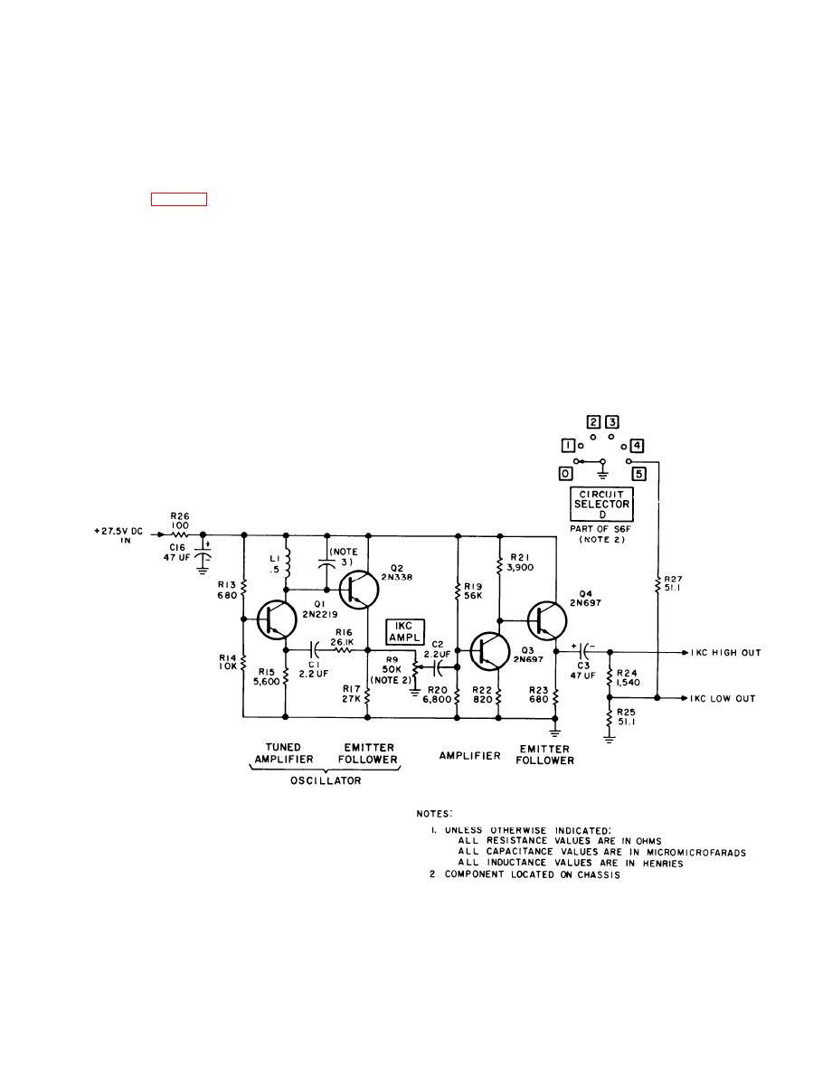
Figure 2-18. 1 kHz oscillator circuit simplified schematic diagram. |
|
||
| ||||||||||
|
|
 TM 11-6625-467-34
Hz) connects to module inputs for various tests. The
does not invert the phase of the input signal; thus
low-level voltage divider output (to the meter) con-
the feedback signal present at the emitter of Q1
nects to the metering circuit for calibration pur-
reinforces the signal at the collector to sustain cir-
poses. The 150 CPS AMPL control adjusts the cir-
cuit oscillation. The L and C parts in the collector
cuit to any desired level.
circuit of Q1 are tuned to 1,000 Hz and cause the cir-
cuit to oscillate at that frequency. Capacitor C2 and
2-23. 1 kHz Oscillator
1 KC AMPL control R9 couple the output of the
oscillator from the emitter of Q2 to the base of am-
The l-kHz oscillator is composed of four transistors
plifier Q3. The 1 KC AMPL control varies the driv-
and associated circuits that produce a 1,000 Hz sine
ing signal to Q3 to provide output amplitude control.
wave at the output. Transistors Q1 and Q2 form a
Amplifier stage Q3 amplifies the 1 kHz signal and
tuned amplifier feedback circuit that oscillates at a
p r o v i d e s a low-impedance l-kHz circuit output.
frequency of 1,000 Hz. The output at the collector of
Resistors R24 and R25 form a voltage divider that
transistor Q1 is directly coupled to the base of Q2.
provides a low-amplitude output at the junction of
The emitter follower circuit of Q2 current-amplifies
the two resistors. In position 5, switch S6F connects
.
the Q1 collector signal and applies it back to the Q1
resistor R27 in parallel with R25 to reduce the low
emitter circuit through the feedback circuit com-
output by one-half.
posed of R16 and Cl. The emitter follower circuit
Figure 2-18. 1 kHz oscillator circuit simplified schematic diagram.
2-59
|
|
Privacy Statement - Press Release - Copyright Information. - Contact Us |
