 |
|||
|
|
|||
|
Page Title:
Recording Head Assembly Test Procedures |
|
||
| ||||||||||
|
|
 TM 11-6625-2478-12
sic of the foil bag along the dotted line. Start the tear at
one corner of the foil bag.
(c) With the side of the foil bag open, tear apart the
front and back of the bag and lift out film pack.
(d) Release four panel fasteners and lift Camera, Still
Picture KE-59A of Case, Test Set CY-7117/AYM-9 by
handles. Lower two hinged sup- porting tubes located
on bottom of Camera, Still Picture KE-59A into holes
provided in base of Case, Test Set CY-7117/AYM-9 to
support free end of Camera, Still Picture KE-59A (fig. 1-
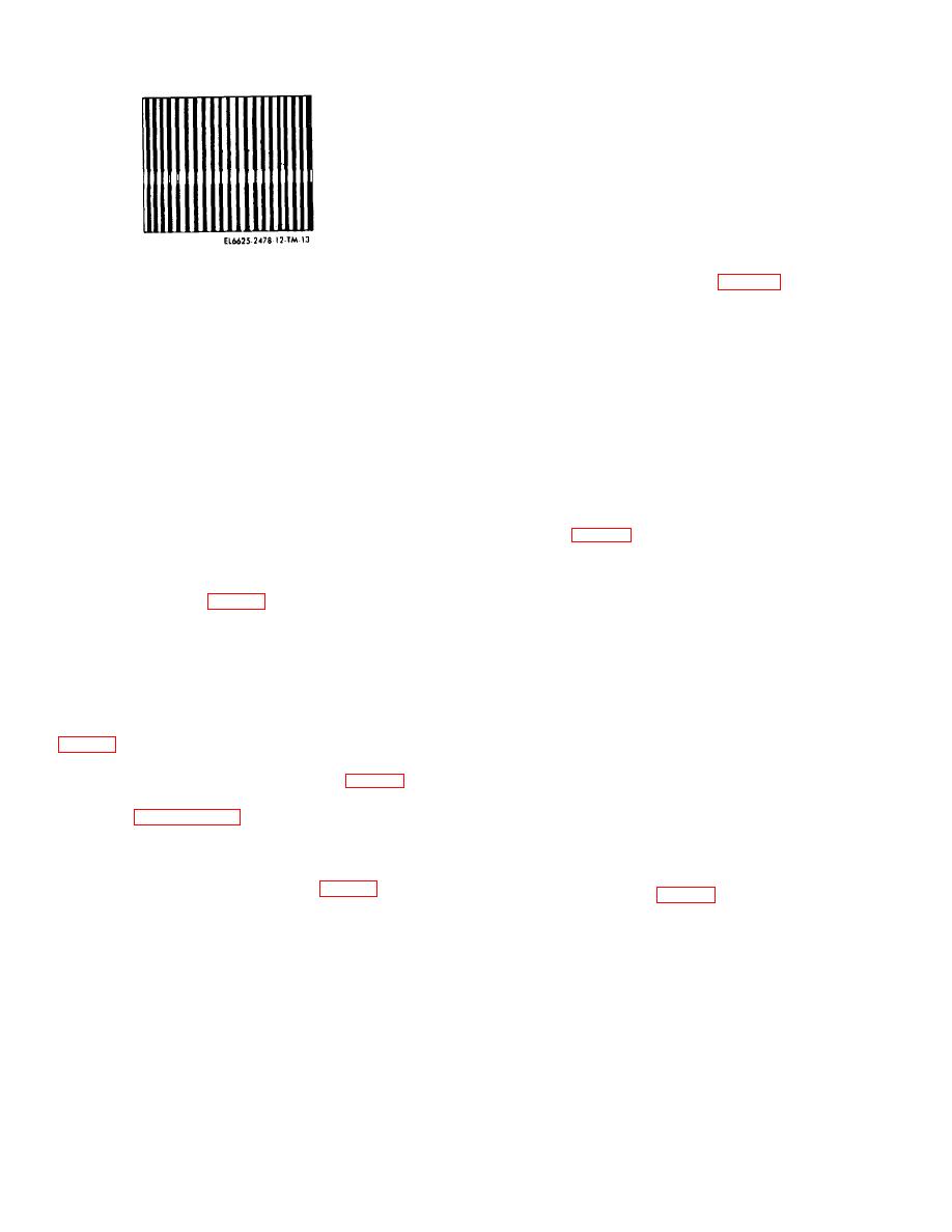
Figure 3-7. Raster Pattern.
40).
3-8. Recording Head Assembly Test
Procedures
end of the camera until back door springs open.
To test a recording head assembly (RHA), perform the
(f) Inspect steel rollers for signs of dirt, dried
preliminary steps described in paragraph a and the test
developer, or lint. If rollers are clean, proceed to step
procedure for the specific type of recording head
(h). If not, perform step (g) before proceeding.
assembly given in paragraph c, d, e, or f.
(g) Lift up red latch securing rollers and swing roller
a. Preliminary Steps.
assembly out. Scrape off any dried developer using a
(1) Release four panel fasteners and lift Cam- era,
bit of cardboard or a matchstick. Wipe rollers clean with
Still Picture KE-59A of Case, Test Set CY- 7117/AYM-9
a damp cloth and dry with a clean lint-free cloth. Swing
by handles. Lower two hinged supporting tubes located
roller assembly into position, making certain red latch
on bottom of Camera, Still Picture KE-59A into holes
engages.
provided in base of Case, Test Set CY-7117/AYM-9 to
(h) Hold film pack so that the printing on the black
support free end of Camera, Still Picture KE-59A (fig.
safety cover faces the lens of the camera. Push closed
14 O).
end of film pack under door hinge against light spring
(2) Remove camera cover assembly, cable re- lease,
pressure (fig. 3-9).
and film from storage compartment in the base of Case,
(i) Gently press film pack down into the cam- era until
Test Set CY-7117/AYM- (fig. 14 O).
it snaps into place. Make certain that white tabs are free
(3) Lift Camera, Still Picture KE-59A of Case, Test
and not folded under the end of film
Set CY-7117/AYM-9 (fig. 1-40) by handles until the two
pack.
hinged supporting tubes located on bottom of Camera,
(j) Close back door, pressing both sides together
Still Picture KE-59A are free of the holes provided in
firmly to be certain that they lock.
base of Case, Test Set CY-7117/ AYM-9. Next, stow
(k) Check that black tab of film pack protrudes
supporting tubes in the clamps provided on underside of
through slot at end of camera. If not, reopen back door
Camera, Still Picture KE-59A.
and place black tab in slot. Then close back
(4) Lower Camera, Still Picture KE-59A of Case, Test
door again.
Set CY-7117/AYM-9 and engage four panel fasteners
(l) Grasp black tab and pull black safety cover
(fig. 1-4 ).
straight out. Pull safety cover all the way out with-
(5) Remove welded plate assembly cover from the
out stopping.
cover of Case, Test Set CY-7117/AYM-9 (fig. 1-5).
(m) When safety cover is out, a white tab will
(6) On the SM-627/AYM-9, set switches to positions
protrude from the slot. Do not pull white tab at this time.
specified in paragraph 3-5.
If no white tab is visible, open back of camera part way,
(7) Connect connector P2 of Cable Assembly,
and without moving the film pack, push white tab
Special Purpose, Electrical CX-2725/U to external side
through the slot. Close and lock back door.
of connector J1 on CY-7117/AYM-9. Connect connector
(n) Lift Camera, Still Picture KE-59A of Case, Test
P1 t connector J3 on SM-627/AYM-9 (fig. 3-3).
Set CY-7117/AYM-9 (fig. 1-40) by handles until the two
b. Operation of Polaroid Camera CU-5.
hinged supporting tubes located on bottom of Camera,
(1) Loading film in the camera. Load camera with
Still Picture KE-59A are free of the holes provided in
Polaroid Land film, Type 107 (3000 speed black and
base of Case, Test Set CY-7117 /AYM-9. Then stow
white film) as follows
supporting tubes in the clamps provided on underside of
(a) Open top of the film box and remove coater
Camera, Still Picture
tube, instruction sheet, and foil bag containing the film.
KE-59A.
CAUTION
Do not press hard on the middle of the film
package or film pack.
(b) Hold film package near the edges and tear open
3-8
|
|
Privacy Statement - Press Release - Copyright Information. - Contact Us |