 |
|||
|
|
|||
|
Page Title:
Section II. OPERATION UNDER USUAL CONDITIONS |
|
||
| ||||||||||
|
|
 TM 11-6625-2478-12
Section II. OPERATION UNDER USUAL CONDITIONS
g. Release seven latches securing the cover of
3-3. Preparation for Use
Case, Test Set CY-7117/AYM-9. Separat the cover
from the base.
a. Place Simulator, Monitor Input SM-627/AYM- 9 on
h. Release four panel fasteners and with the handles,
a work bench or other suitable area convenient to a 115
lift Camera, Still Picture KE-59A of Case, Test Set CY-
volts at 400 Hz power source. b. Press the core of the
7117/AYM-9. Lower two hinged sup- porting tubes
pressure relief valve on Simulator,
monitor Input
located on the bottom of Camera, Still Picture KE-59A
SM27/AYM-9 (fig. 1). Allow the internal pressure to
into the holes provided in the base of Case, Test Set
equalize with atmospheric pressure (approximately 30
CY-7117/AYM-9 to support the free end of Camera, Still
seconds).
Picture KE-59A (fig. 1J4 0).
c. Release seven latches securing Cover, Test Set
I. Remove all cable assmblies from storage area in
CW-1149/AYM-9 of Simulator, Monitor Input SM-
base of Case, Test Set CY-7117/AYM-9.
627/AYM-9. Separate Cover, Test Set CW-1149/ AYM-
j. Lift Camera, Still Picture KE-59A of Case, Test
9 from e base.
Set CY-7117/AYM-9 (fig. 14 @ ) by handles until the
d. Place Simulator, Monitor Input SM 627/AYM- 9 in
two hinged supporting tubes located on bottom of
upright position.
Camera, Still Picture KE-59A are free of the holes
e. Place Case, Test Set CY-7117/AYM-9 on the work
provided in base of Case, Test Set CY-7117/AYM-9 and
bench adjacent to Simulator, Monitor Input SM627/AYM-
stow the supporting tubes in the clamps provided on the
9.
underside of Camera, Still Picture KE-59A.
f. Press the core of the pressure relief valve on
k. Lower Camera, Still Picture KE-59A of Case, Test
Case, Test Set CY-7117/AYM-9 (fig. 14). Allow the
Set CY-7117/AYM- and engage four panel fasteners (fig.
internal pressure to equalize with atmospheric pressure
14 ).
(approximately 30 seconds).
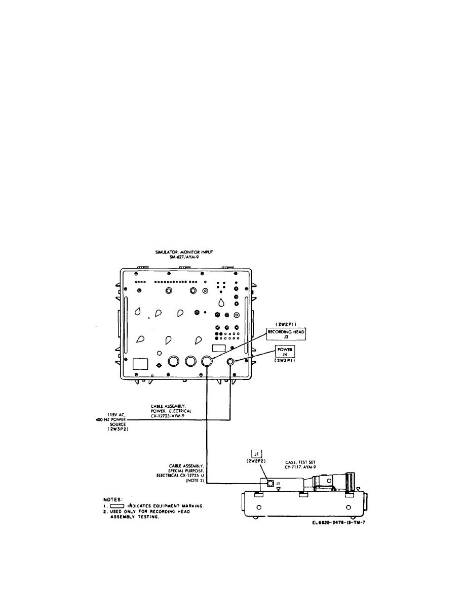
Figure 3-3. Test Set Control Monitor-Recording Head AN/A YM-
9, cable interconnection diagram.
3-5
|
|
Privacy Statement - Press Release - Copyright Information. - Contact Us |
