 |
|||
|
|
|||
|
Page Title:
Chapter 2. OPERATING INSTRUCTIONS |
|
||
| ||||||||||
|
|
 TM 9-4931-378-13&P
OPERATING INSTRUCTIONS
Section I. GENERAL
accordance with the instructions of TM 38-750.
The equipment should be placed in service even
case, All interconnecting test cables and fixtures are stored
though a minor assembly or part that does not
in a compartment in the case cover. Upon original receipt,
affect proper functioning is missing.
only the removal of the case from the packing container is
Check to see whether the equipment has been
c.
required to prepare the equipment for use. The following
modified. (Equipment which has been modified
equipment is included in the test set:
will have the MWO number on the front panel near
the nomenclature plate.) Check also to see
Test Set, Air Data Subsystem
whether all currently applicable MWO have been
Fixture, Checking
applied. (Current MWO applicable to the equip-
Kit, Pneumatic
ment are listed in DA PAM 310-7.)
Tubing (5 four-foot lengths)
AC Power Cable Assembly W1
DC Power Cable Assembly W2
t e c t e d from overload and short circuit conditions by
LAI Cable Assembly W3
internal protective devices. No damage can be caused
EPU Cable Assembly W4
through normal use of front panel controls. However,
AADS Cable Assembly W5
normal precautions must be exercised to avoid injury to
Adapter Assembly W6
personnel. Shut off bench power (115 Vac and 28 Vdc)
before connecting or disconnecting the power cables W1
2-2. Initial Inspection. After unpacking, the following in-
and W2. When connecting or disconnecting cables W3
spection procedure shall be performed:
through W5, be sure that circuit breakers CBI and CB2 are
a. Inspect the equipment for damage incurred during
OFF.
shipment. If the equipment has been damaged,
report the damage on DD Form 6.
b. Check the equipment against the component list-
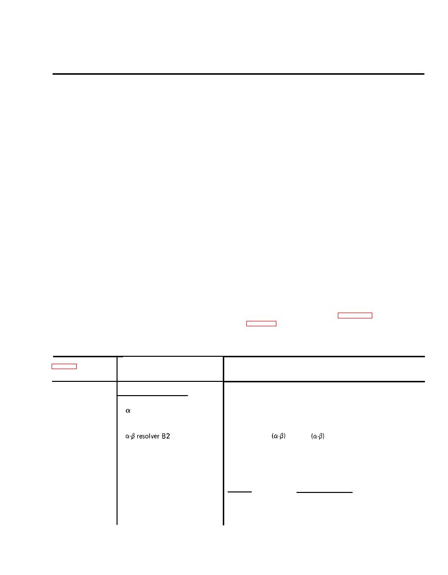
and connectors are shown in figure 2-1 and explained in
ing in the manual and the packing slip to see if the
description.
shipment is complete. Report all discrepancies in
Control, Indicator
Index No.
or Connector
Function
EPU TEST SECTION
Generates sin α and cos α analog signals to simulate AADS
resolver B1
1
outputs for testing the EPU.
and cos
analog signals to simulate
Generates sin
2
AADS outputs for testing the EPU.
Displays 8-bit binary word. Bit 0 is LSB and Bit
DATA WORD binary display
3
7 is MSB.
Indicators DS1 through DS8
Sw Pos
Specific
Functions
DATA MODE three position
4
toggle switch S1
CONT
Selects continous data from EPU
HOLD
Selects hold mode of data from EPU
RPT
Selects repeat of data from EPU
|
|
Privacy Statement - Press Release - Copyright Information. - Contact Us |