|
| |
TM 55-6695-220-13&P
d.
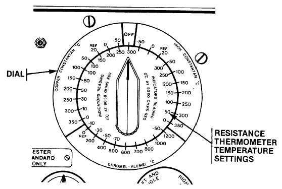
The second function of the RESISTANCE AND VOLTAGE FUNCTION SWITCH is to select precision resistors
for application to the resistance thermometer circuit. These resistance values correspond to that which a platinum wire
coil in one leg of a ratiometer would attain at the temperature marked on the dial. The RESISTANCE AND VOLTAGE
FUNCTION SWITCH has two ranges of temperatures: one for a bulb resistance of 50 ohms at 0°C and the other 90.38
ohms at 0°C. These resistances are applied to the resistance thermometer circuit through the five conductor circular
connector. The errors of the test resistance thermometer are the differences noted between the indicator readings and
the markings on the temperature dial. Consult the manual about the significance of these errors and whether the
resistance thermometer should be returned to service. At the completion of the test return the RESISTANCE AND
VOLTAGE FUNCTION SWITCH to the OFF position to conserve battery energy.
Section II. PREVENTIVE MAINTENANCE CHECKS AND SERVICES (PMCS)
2-4.
GENERAL.
2-4
After the completion of a test use a soft cloth to wipe the accumulated dust and finger prints off of the instrument panel
and viewing glass on the voltmeter. Unlatch the battery compartment cover and check to see if the batteries are leaking
corrosive battery chemical. If a battery case is found to be leaking remove the defective item and initiate procedures to
have the battery replaced. With the tester
2-12
|

