|
| |
TM 55-6695-220-13&P
b.
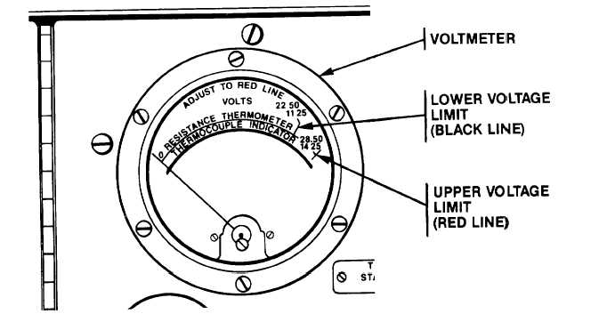
The RESISTANCE THERMOMETER scale on the VOLTMETER shows two voltage ranges: 11.25 (Black) to
14.25 volts (Red) and 22.50 (Black) to 28.50 volts (Red). One of these two voltage ranges is selected by rotating the
RESISTANCE AND VOLTAGE FUNCTION SWITCH to the corresponding nominal 12 or 24 volt position. Consult the
appropriate manual to learn the exact excitation voltage required for the test indicator. Adjust the COARSE RHEOSTAT
to position the VOLTMETER pointer to the required excitation voltage.
c.
When testing a single resistance thermometer or the left side of a dual unit place the LEFT AND SINGLE
SWITCH to the corresponding position; and when testing the right side of a dual unit place the switch pointer to RIGHT.
This excitation voltage now appears at one of two possible connector pin pairings while the other pairing has a 100 ohm
damping resistor connected across it.
2-11
|