 |
|||
|
|
|||
|
Page Title:
CHAPTER 2. OPERATING INSTRUCTIONS |
|
||
| ||||||||||
|
|
 TM 55-4920-415-13&P
CHAPTER 2
OPERATING INSTRUCTIONS
SECTION I. INSTRUMENTS AND CONTROLS
2-1. General. Information relative to the location and
located on the base (16) are used to level the tester.
function of the controls and instruments necessary to
operate the gyro tester is contained in this section. A
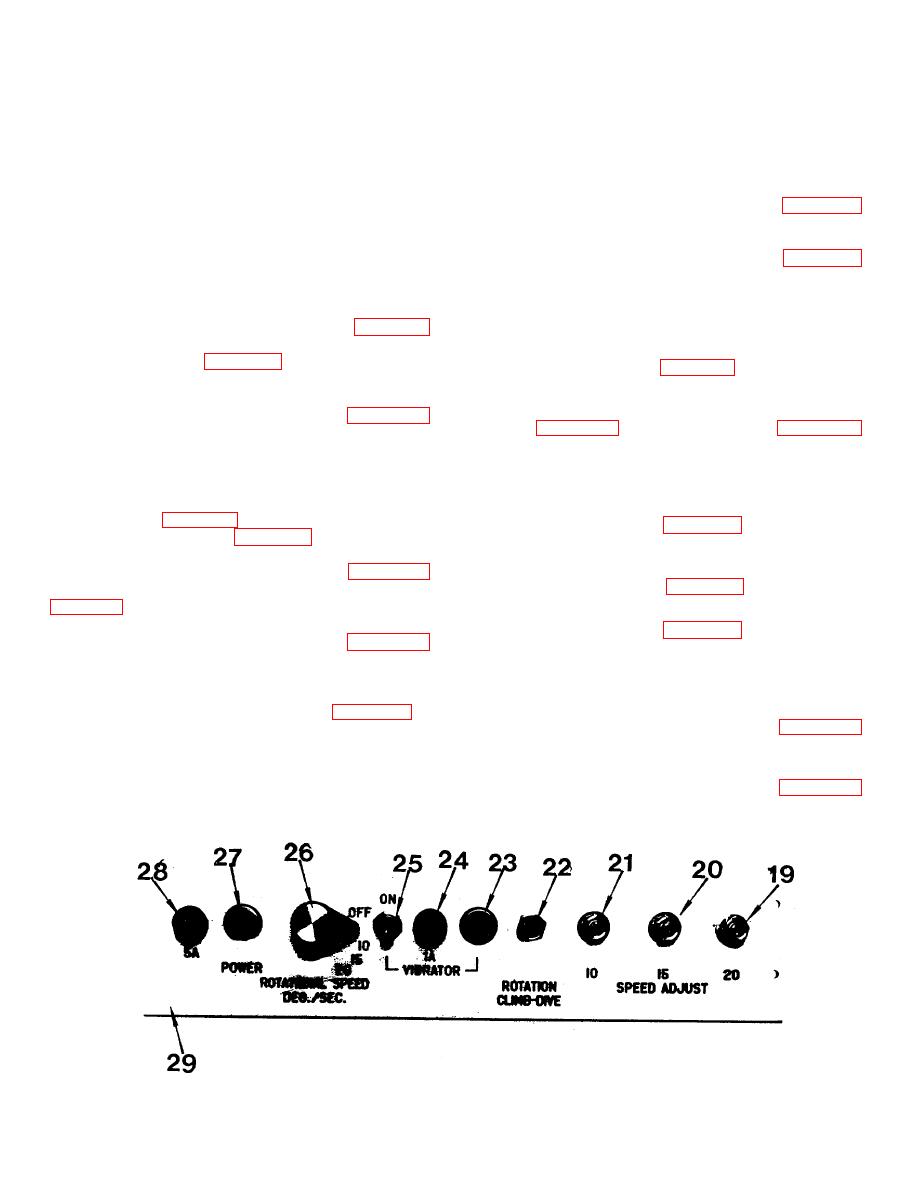
close-up picture of the control panel (29) is shown in
Figure 2-1.
and (9) are used as visual aids in leveling the unit.
2-2. Rotation Switch. This is a three position toggle-
2-10. Indicator Light.
type switch located on the control panel (22, Figure 2-1)
which energizes, de-energizes or reverses the direction
a. When ac power has been applied to the unit
of the drive motor (10, Figure 1-1).
indicator light (27, Figure 2-1) glows.
b. When ac power has been applied to the vibrator
2-3. Rotational Rate Switch. This four position rotary
motor through application of toggle switch (25,
switch located on the control panel (26, Figure 2-1)
applies ac power to the gyro tester, and at the same
glows.
time, selects the rotational rate for the gimbal ring-fork
assembly in steps of 10, 15, or 20 degrees per second.
2-11. Rotation Rate Adjust Control.
2-4. Vibrator Motor Switch . This two position toggle-
type switch (25, Figure 2-1) located on the control panel
a. Potentiometer (19, Figure 2-1) is used to set the
turns the vibrator motor (8, Figure 1-1) "ON" or "OFF".
20 degrees per second rotational rate of the
gimbal ring-fork assembly.
b. Potentiometer (20, Figure 2-1) is used to set the
mounted on the base is used to lock the cradle (15,
15 degrees per second rotational rate.
c. Potentiometer (21, Figure 2-1) is used to set the
10 degrees per second rotational rate.
located on the fork (7) locks the gimbal ring (6) in a
plane either parallel to, or at a right angle to the fork.
2-12. Fuse Holder.
a. A 5 ampere fuse in location (28, Figure 2-1)
mounted on the fork and in the engaged position locks
provides electrical protection for the unit from
the gimbal ring-fork assembly in either the 0 degree or
the incoming ac power.
360 degree positions (after one full turn). By pulling the
knob and twisting it one-quarter turn clockwise or
b. A 1 ampere fuse in location (24, Figure 2-1)
counterclockwise, it disengages allowing the fork to turn
provides electrical protection for the vibrator
continuously.
motor.
Figure 2-1. Control Panel.
2-1
|
|
Privacy Statement - Press Release - Copyright Information. - Contact Us |