
TM 5-6350-264-14&P-8
NAVELEX EE181-AA-OMI-090/E121 SA-1954
T.O. 31S9-2FSS9-1-8
CHAPTER 2
OPERATING INSTRUCTIONS
Section I. OPERATING PROCEDURES
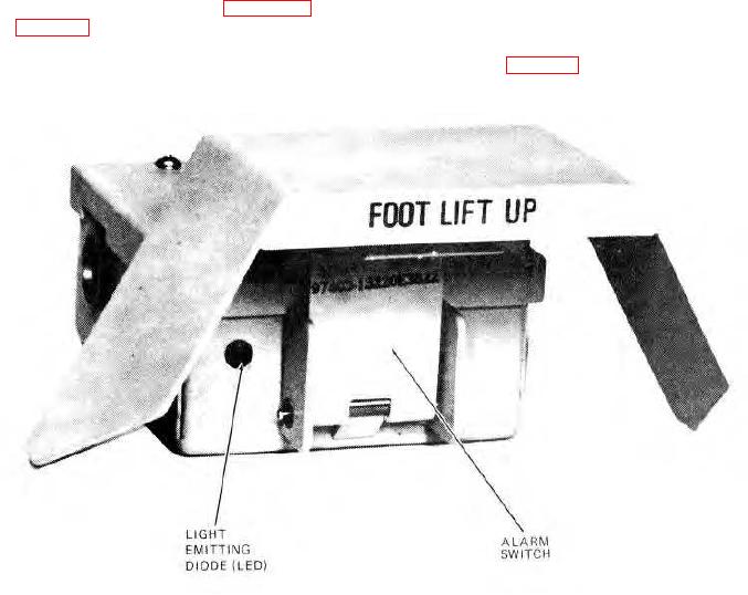
2-1. CONTROLS AND INDICATORS. The LAS operator
tested, and connected to the J-SIIDS Control Unit.
controls and indicators are shown in figure 2-1 and
Since the startup and shutdown of the LAS are
described in table 2-1.
dependent on the presence or absence of power from
the control unit, no operating procedures other than
2-2. NORMAL OPERATING PROCEDURES. The LAS
those listed in table 2-1 are required.
is
operational
after
it
has
been
installed,
Figure 2-1. LAS Controls and Indicators
2-1