
TM 5-6350-264-14&P-8
NAVELEX EE181-AA-OMI-090/E121 SA-1954
T.O. 31S9-2FSS9-1-
(4) No alarm. The LAS is in the no-alarm state when
is moved, the normally low resistance across the tamper
switch terminals is changed to high resistance which is
a circuit impedance of 2000 ohms or less is present
used as the tamper alarm signal. When the cover is
across TB1-1 and TB1-2 and TB1-5 and TB1-6.
installed, the tamper alarm switch is restored to the no-
alarm state.
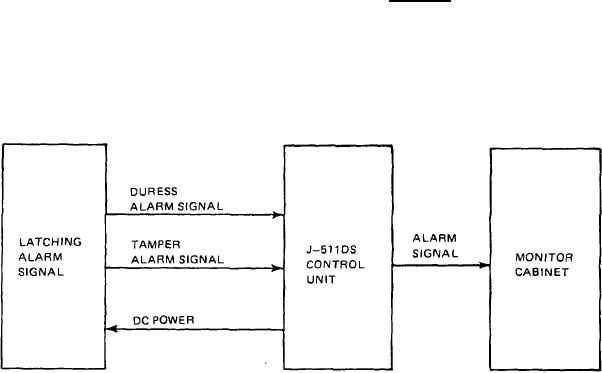
Figure 2-2. LAS Simplified Functional Block Diagram
2-3/(2-4 blank)