
TM 5-6350-264-14&P-2
NAVELEX EE181-AA-OMI-030/E121 RT1161 M9443
T.O. 31S9-2FSS9-1-2
(1) Inspect the equipment for evidence of physical
damage.
NOTE
(2) Inspect the terminal strips for clean and secure
Touchup paint is recommended instead of refinishing
connections.
whenever practical.
(3) Inspect all wiring and cabling for worn or frayed
(6) Inspect all metal surfaces intended to
insulation and broken wires.
be painted for condition of finish and
legibility of panel lettering.
(4) Inspect all resistors for discoloration due to
overheating.
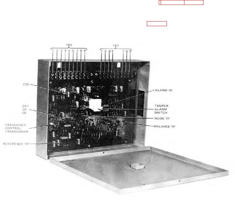
f. Refer to figures 5-1 and 5-2 for all test points
found in the troubleshooting table. Step-by-step
(5) Inspect the complete subsystem for the
troubleshooting procedures, including troubles,
presence of dirt, corrosion, moisture, and bits of
probable cause, and corrective action, are listed
wire or solder inside the housings.
in table 5-1.
Figure 5-1. Processor, With Troubleshooting Test Points
5-2