
TM5-6350-264-14&P-12
NAVELEX EE 181.AA-OMI-120/E121 C-7359-60-1
TO 31S9-2FSS9-1-12
Table 5-l. Troubleshooting Procedures - Continued
Corrective action
Trouble
Probable cause
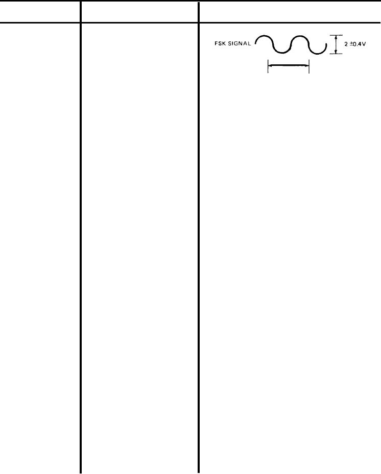
e. (cont)
2. (cont)
Hz)
0.91 TO 0.96 MS (1037.9 to 1102.1
e. The multimeter, still connected to A4-
TP7 and TP3, should indicate less than
1 vdc. Maintain this check for a period
of time to ensure that this voltage is
stable.
f. If the clock, or FSK signal, or voltage
changes, replace Data Receiver.
(1) To remove Data Receiver, turn off
switch Sl on power supply. Re-
move screws that secure status
monitor module to rack and re-
move module through front of
rack. Remove string or tape
and loosen captive screws and
remove Data Receiver from
bottom of module. Remove code
plug from its socket on PC board A1.
(2) To replace Data Receiver, remove
screws that secure cover and re-
move cover from new Receiver.
Position code plug from old Re-
ceiver over socket X1 on PC board
A1. Turn code plug so that painted
dot or notched comer on plug lines
up with dot on PC board. Carefully
push plug into socket. Replace cov-
er and secure with screws. Plug Re-
ceiver into status monitor module.
Tighten four captive screws to se-
cure Receiver to status monitor
module. Replace status monitor
module in swingout rack and secure
with screws. Turn on switch S1 on
power supply. Wait one or two min-
utes for system to stabilize; then
push RESYNC button in CU. Re-
move all test leads and test equip-
ment from Data Transmitter and
Data Receiver.
5-31