
TM 5-6350-264-14&P-12
NAVELEX EE 181-AA-OMI-120/E121 C-7359-60-1
TO 31S9-2FSS9-1-12
Table 5-1. Troubleshooting Procedures - Continued
Trouble
Probable cause
Corrective action
2. (cont)
c. (cont)
Turn code plug so that painted
dot or notched comer on plug
lines up with dot on PC board.
Carefully push plug into socket.
Replace cover and secure with
screws. Plug Receiver into status
monitor module and tighten
captive screws to secure Receiver
to status monitor module. Re-
place status monitor module in
swingout rack and secure with
screws. Turn on switch S1 on
power supply. Wait one or two
minutes for system to stabilize;
then push RESYNC button in
cu.
d. Bad Data
a. If voltages are stable, check Data Trans-
Transmitter.
mitter clock and FSK signals for
changes. Turn off switch S1 on CU
power supply and remove screws that
secure Data Transmitter to standoffs
in CU. Carefully move Transmitter
so that test points on PC board A1
can be reached. Turn on switch S1
power supply. Set oscilloscope as
follows:
volts/division
@2v
time/division
@10ms
input
@dc
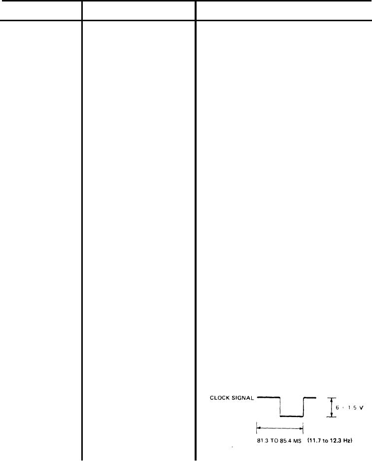
Connect scope probe to A2-TP2, red.
Connect scope ground to Transmit-
ter chassis. The scope should display
clock signal as a squarewave of 6
1 vdc, and 85.4 to 81.3 ms (11.7
to 12.3 Hz). Maintain this check
for a period of time to ensure that
clock signal is stable.
5-26