TM 5-6350-264-14&P-10
NAVELEX EE 181-AA-OMI-110/E121 C-9412
T.O. 31S9-2FSS9-1-10
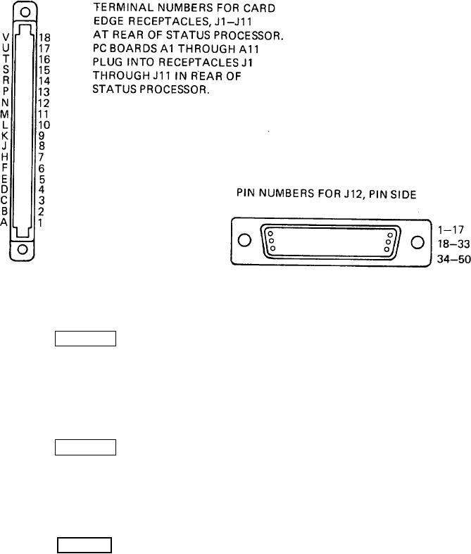
Figure 5-4. Status Processor Connector Identification
proper scale and range before inserting
WARNING
probes into the circuit.
The Audible Alarm presents a noise
NOTE
hazard to personnel in the area. The
noise level exceeds the allowable limits for
unprotected personnel. Authorized
If the Audible Alarm is installed, it must be
protective equipment must be worn by all
disabled BEFORE any troubleshooting
personnel in the work area.
procedures are attempted. Disabling the
alarm requires setting the key-operated
switch on Control Unit to TEST/ RESET
WARNING
position, opening Audible Alarm, removing
faceplate, and turning off power switch.
While performing maintenance or troubleshooting on the
After troubleshooting, the Audible Alarm
Control Unit, ensure that test points and terminals are
must be reactivated. Activating the Alarm
never grounded or shorted to each other or to chassis.
requires setting the key operated switch on
This will cause serious damage to the internal
Control Unit to TEST/RESET position,
components.
turning Alarm power switch on, replacing
faceplate, closing and locking Audible
CAUTION
Alarm door.
When taking measurements with a
multimeter, ensure that the meter is set to
the
5-6

