Home
Download PDF
Order CD-ROM
Order in Print
Figure 5-1. Maintenance Controls and Indicators
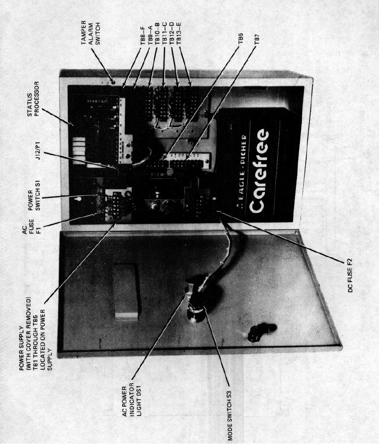
Figure 5-3. Control Unit Switch Identification
Maintenance Manual For Control Unit, Alarm Set C-9412/Fss-9(V) -10
Page Navigation
7
8
9
10
11
12
13
14
15
16
17
TM
5-6350-264-14&P-10
NAVELEX
EE
181-AA-OMI-110/E121
C-9412
T.O.
31S9-2FSS9-1-10
Figure
5-2.
Control;
Unit
troubleshooting
Test
Points
5-4