 |
|||
|
|
|||
|
|
|||
| ||||||||||
|
|
 TM 11-6625-646-15
e. Set the 115V 400 ~ POWER switch to on (up)
b. Differential Pressure.
position.
(1) Connect the manometer to the L and R air
connections on the TS-1894/ASM.
Use the hose
f. Check for 24 to 28 volts ac between pins 12 and
assemblies furnished.
18.
(2) Set the PUMP switch to on (up) position.
g. Set the 115V 400 ~ POWER switch to off
(down) position.
(3) Adjust the DIFF. PRESSURE to the
indications in table 7-2. The manometer pressures
h. If any indication is not as specified, take
should be as specified in the table.
corrective action and repeat the applicable steps.
(4) Set the PUMP switch to its off (down)
position.
7-12. Half-Gain Circuits Test
a. Connect a jumper between TEST POINTS E
(5) Disconnect the hose assemblies.
and G.
(6) If any indication is not as specified, take
b. Connect a 200-ohm, 5-watt resistor between
corrective action and repeat the applicable steps.
TEST POINTS A and C.
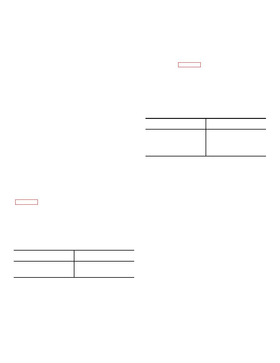
Table 7-2. DIFF. PRESSURE Indicator Test
c. Set the 115V 400 ~ POWER switch to up (on)
position. Check that the FULL GAIN indicator is on.
DIFF. PRESSURE
Manometer pressure
d. Press the HALF-GAIN switch. Check for 28 to
Indication (inches)
(inches)
36 volts dc at TEST POINTS F.
3.5R
3.33 to 3.67
e. Release the HALF-GAIN switch. Disconnect the
14R
13.3 to 14.7
jumper and resistor.
3.5L
3.33 to 3.67
f. If any indication is not as specified, take
14L
13.3 to 14.7
corrective action and repeat the applicable steps.
0
0
7-13. Pneumatic Components Test
7-14. Adapter Circuits Test
a. Airspeed.
(1) Connect the manometer to the P and S
OFF. Turn the GAIN SWITCH to AIR.
air connections on the TS-1894/ASM. Use the hose
b. Check for 0 ohm between corresponding pins of
assemblies furnished.
J101 and P101 except pins j, h, f, and B.
(2) Set the PUMP switch to on (up) position.
c. Check for 0 ohm between J101 pins j and f and
(3) Adjust AIRSPEED to the indications in
TB101 terminals 6, 7, and 10. Check for 0 ohm
between J101-h and TB101-13. Check for 0 ohm
specified in the table.
between J101-B and TB101-12.
(4) Set the PUMP switch to off (down)
d. Connect the ac power supply between J101 pins
position.
p and C (ground). Adjust the ac supply to 26 volts.
(5) Disconnect the hose assemblies.
Check for 12.38 to 13.64 volts ac between J101 pins h
(6) .If any indication is not as specified, take
and C. Use the vtvm.
corrective action and repeat the applicable steps.
e. Connect the vtvm between J101 pins f and j.
f. Turn the ROLL GYRO SIMULATOR switch R
Table 7-1. AIRSPEED Indicator Test
LIM and then to L LIM. The vtvm should indicate
AIRSPEED
Manometer
between 2.71 and 2.99 volts ac.
indication (knots)
pressure (inches)
80
3.99 to 4.41
ROLL and then to R ROLL. The
150
13.6 to 15.0
0
0
71
|
|
Privacy Statement - Press Release - Copyright Information. - Contact Us |
