 |
|||
|
|
|||
|
Page Title:
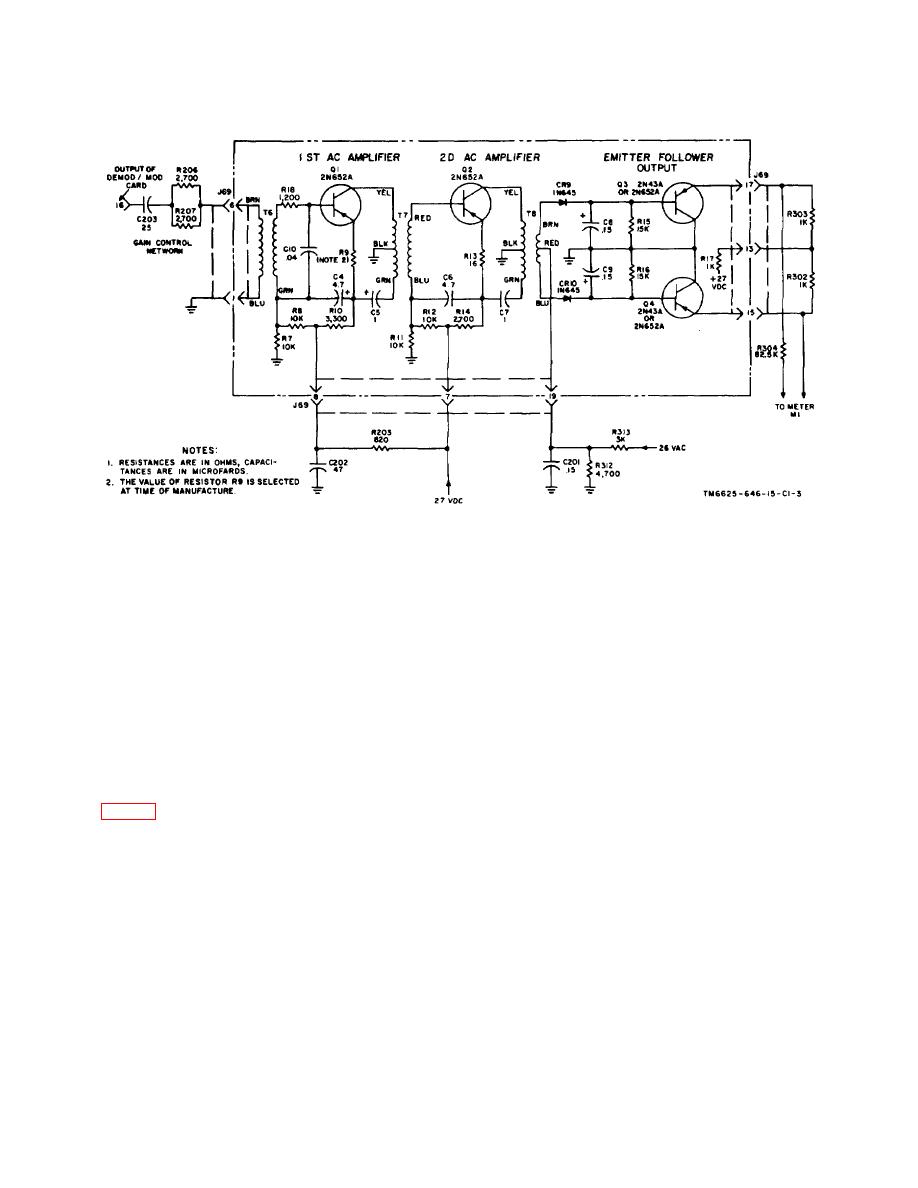
Figure 1-3. Amplifier card, schematic diagram. |
|
||
| ||||||||||
|
|
 TM 11-6625-646-15
C1
Figure 1-3. Amplifier card, schematic diagram.
a. When FUNCTION switch S7 is at DC PWR, the
c. Output Signal.
The output signal of the
output of the 27-volt dc supply of the test set is
amplifier card is routed through pins 13, 15, and 17 of
connected to meter M1 through multiplier resistor R201.
receptacle J71 and is applied across torque motor
simulator load resistors R306 and R307 (on card
b. When FUNCTION switch S7 is at PEDAL POT.
A02V3064). Connections to the function meter M1 are
EXCITATION, the positive and negative 18-volt
routed from pins 7 and 10 of receptacle J67 through the
excitation from the SAS amplifier (for the pedal position
AMPL OUPT position of FUNCTION switch wafers S7A
variable resistor) is connected to meter M1 through
and S7B. Resistor R307 (on card A02V3064) is a meter
multiplier resistor R301.
multiplier.
c. When FUNCTION switch S7 is at INTLK the 28-
volt dc interlock voltage from the SAS amplifier (for the
1-30. Function Meter Circuits
gain control relay in the other SAS amplifier of a dual
system) is connected to meter M1 through multiplier
1-31. Dc Metering Circuits
resistor R202.
d. When FUNCTION switch S7 is at DEM OUPT,
During dc metering functions, all connections to
the differential output of amplifier card P69 in the test
FUNCTION meter M1 are made through FUNCTION
set, applied across load resistors R302 and R303, is
switch wafers S7A and S7B and a selected meter
connected to meter M1 through multiplier resistor R304.
multiplier resistor. For each position of switch S7 the
e. When FUNCTION switch S7 is at AMPL OUPT,
meter multiplier resistor has a value which results in a
the differential output of the amplifier card (not shown)
meter indication within the red or green sector of the
in AMPLIFIER receptacle J71, applied across load
scale.
resistors R306 and R307, is connected to meter M1
13
|
|
Privacy Statement - Press Release - Copyright Information. - Contact Us |
