 |
|||
|
|
|||
|
|
|||
| ||||||||||
|
|
 the additional equipment used in the
(4) Inspect the seating of interconnecting
test procedure.
and test cables. Use direct pressure
to insure they are firmly seated.
(5) See that there are no loose or missing
URM-105 to check for continuity (0 ohms re-
screws. Tighten loose screws, and re-
sistance) between the connectors on each of
place any that are missing.
the cables.
cable, and adapter cable. These cables
19. Troubleshooting
have only single center conductors and
If the equipment fails to perform properly,
ground connections.
turn off the power to all additional equipment
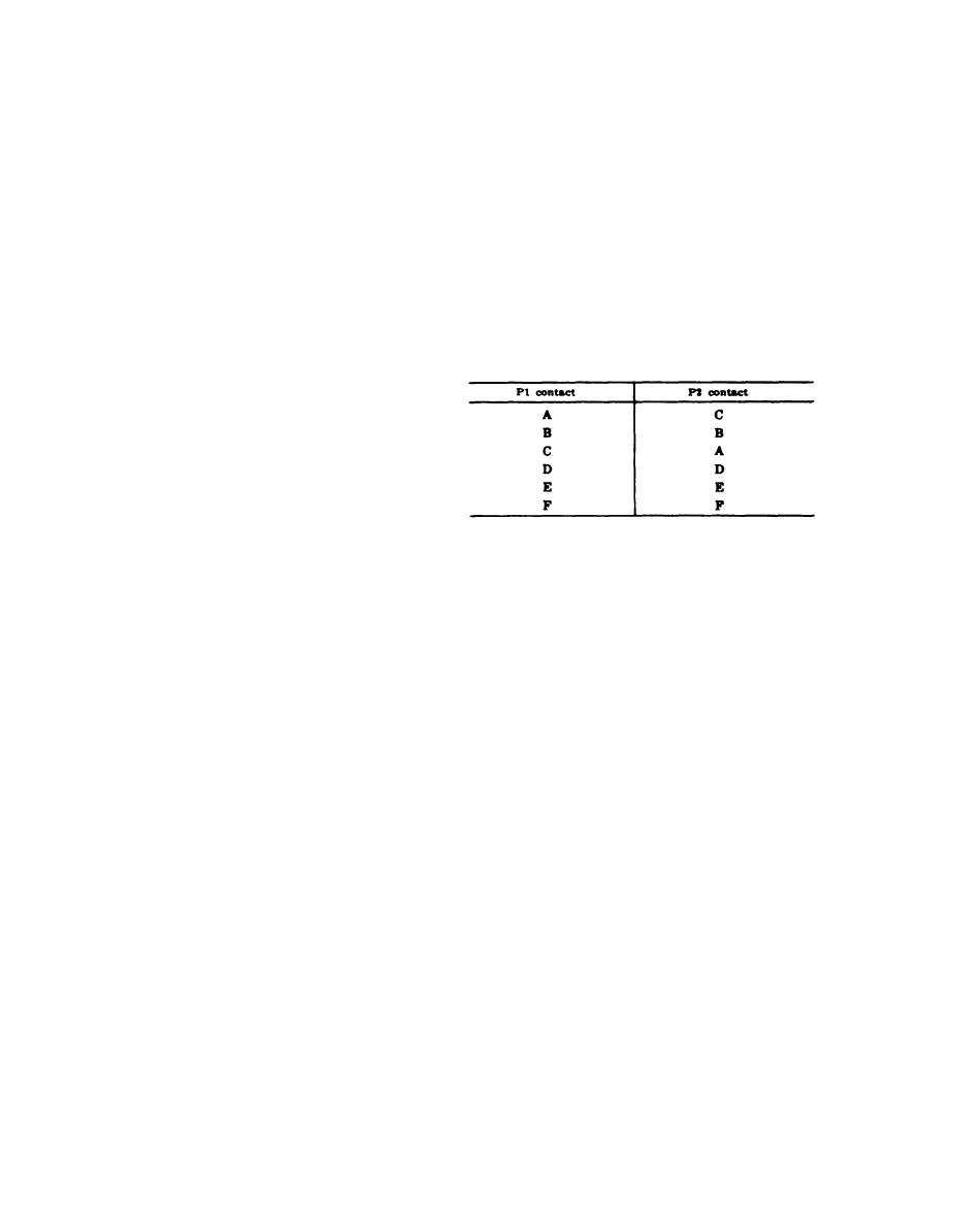
(2) Test cables. Each of these cables has
used in the test procedure. Perform the checks
six connections which are used. Both
indicated in a and b below. If these checks do
cables are wired in the following man-
not locate the trouble, troubleshooting at a
ner:
higher echelon of maintenance is required. Note
on the repair tag how the equipment performed
at the time of failure.
a. Visual Inspection. Check the equipment
for the following possible causes of malfunc-
tion:
(1) Test or interconnecting cables loosely
or improperly connected.
(2) Incorrect settings of switches or con-
Note. On the selector test cable P1 and P2 are identical. On
the indicator test cable P1 is the plug which connects to the
trols on either the resolver test set or
course indicator.
16
|
|
Privacy Statement - Press Release - Copyright Information. - Contact Us |