 |
|||
|
|
|||
|
Page Title:
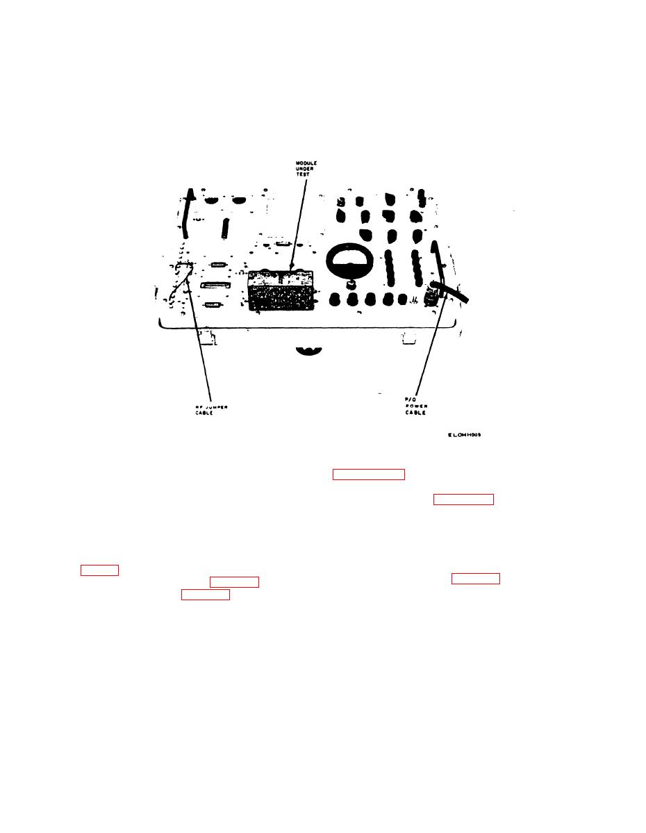
Figure 3-2 Test set typical test bench setup |
|
||
| ||||||||||
|
|
 TM 11-6625-467-12
mating connector on the front panel. (The module
screws to insure a good electrical and mechanical
names are etched on the front panel near the
connection.
associated connector.) Tighten the module captive
Figure 3-2 Test set typical test bench setup
d. Operating Procedure Switch and Control Set-
to paragraph 3-3 for explanation of chart headings.)
tings. Unless otherwise directed by the operating
Upon completion of test and/or tests, perform the
procedures, all test set controls should be rotated to
s t o p p i n--g procedure (para 3-14).
--
the extreme counterclockwise position, the POWER
NOTE
SELECTOR switch set to NORMAL, and the
The modules (low frequency oscillator
POWER switch set to ON.
(lfo), high frequency oscillator (hfo),
variable if., rf amplifier and power am-
3-6. Rf Subchassis Test
plifier) referred to in the instructions of
test name columns of table 3-2 below are
Perform the starting procedure (para 3-5) before
mounted on the rf subchassis under test.
proaeding with the tests in table 3-2 below. (Refer
3-6
|
|
Privacy Statement - Press Release - Copyright Information. - Contact Us |
