 |
|||
|
|
|||
|
Page Title:
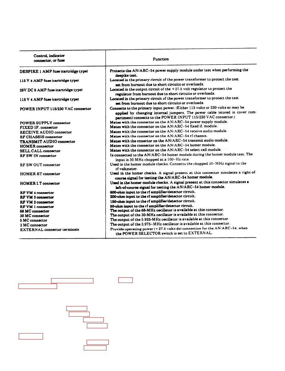
Table 3-1. Operator's Controls - Continued |
|
||
| ||||||||||
|
|
 TM 11-6625-467-12
Table 3-1. Operator's ControlsContinued
Section Il. OPERATION
b. Explanation of Table Headings.
3-3. General Operating Procedures
(1) Step. Several tests may be performed on
a. Module Tests. The tests that can be performed
each module; the step column indicates the number
on the various AN/ARC-54 modules are presented
of the particular test being performed. Each num-
i n tables in paragraphs 3-6 through 3-12.
bered step is a complete test in itself and may be
performed independently.
power to a complete AN/ARC-54 radio set. The
(2) Test name. The test name column indicates
AN/ARC-54 modules that can be tested are listed in
the name of the circuit or signal function that is
(1) through (7) below.
being tested 1 Refer to TM 11-5821-244-35 for the
(1) Rf subchassis (para 3-6).
schematic diagrams covering the AN/ARC454
(2) Homer module (para 3-7).
modules
(3) Receive audio module (para 3-8).
(3) CIRCUIT SELECTOR switches. The CIR-
(4) Transmit audio module (para 3-9).
CUIT SELECTOR switches column indicates the
(5) Fixed intermediate frequency (if.) module
positions of the CIRCUIT SELECTOR switches (A,
B, C, and D) for the test being performed. An X in
(6) Select (sel) call module (para 3-11).
this column indicates that the position of that par-
(7) Power supply module (para 3-12).
3-4
|
|
Privacy Statement - Press Release - Copyright Information. - Contact Us |
