 |
|||
|
|
|||
|
Page Title:
ELECTRICAL CONNECTIONS |
|
||
| ||||||||||
|
|
 TM 11-6625-3024-14/EE641-AC-MMA-010/E154 SYSEX/TO 33AA50-5-1-1
11. Press the LAMP TEST switch located on
CAUTION
the top connector panel. Verify that all indicators
Do not turn on power without first
light except TRANSPORT power switch (located
checking to ensure that no indica-
above SYSTEM ON/off switch) and the nine write
tor lamps are missing from socket.
data indicator switches.
Burnout of transistor driver will oc-
(cur if lamp is missing.
12. Ensure that the TRANSPORT ON/OFF in-
dicator is extinguished. Press the SYSTEM ON/
9. Press the front panel SYSTEM ON/OFF
OFF switch to remove power from the Exerciser
switch to turn power on.
before connecting the interconnecting cables to
the transport.
10. Press the PROCESSOR RESET switch lo-
cated on the top connector panel (Figure 3-2).
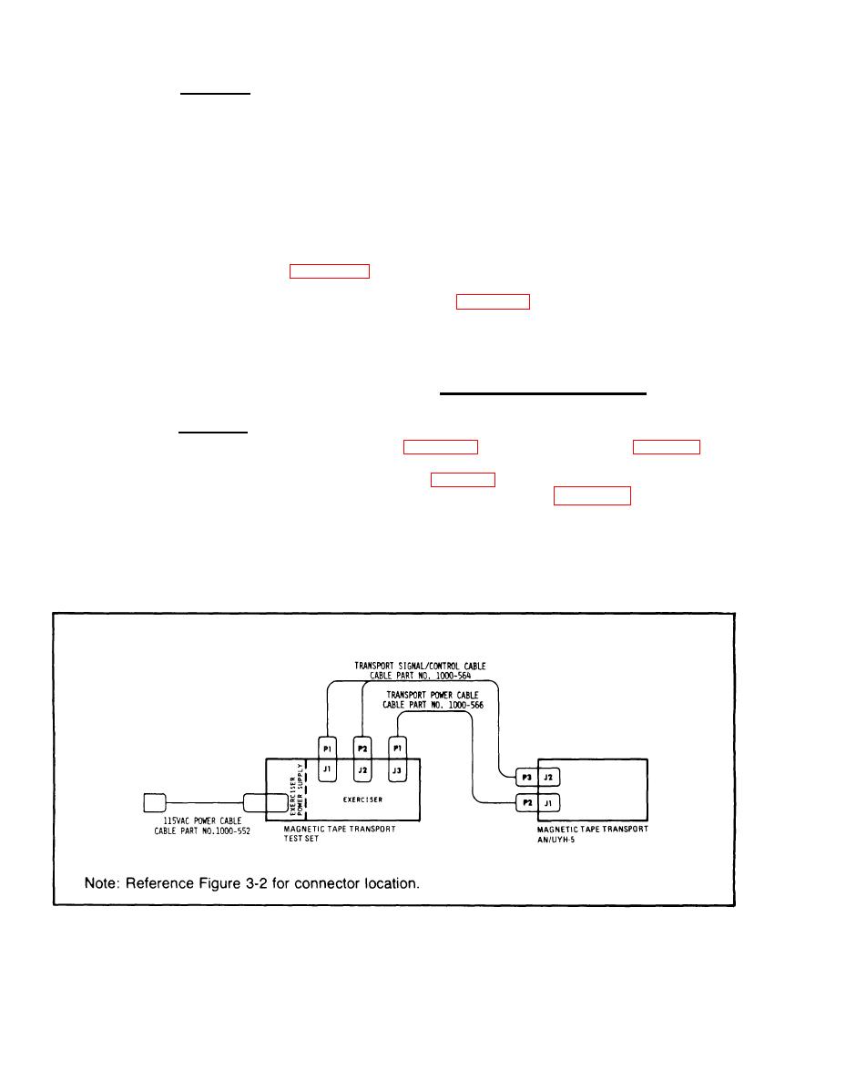
13. Attach transport signal/control cable P3 to
Verify that all front panel indicators are extin-
J2 (see Figure 2-1) and transport power cable P2
guished, except SYSTEM ON/OFF power switch,
to J1 on the Magnetic Tape Transport AN/UYH-5.
STOP switch, WRITE RESET, Data Select indi-
cators, and Error indicators.
14. Insert tape in transport and close door,
2-4. ELECTRICAL CONNECTIONS
All electrical connections from the Exerciser to
CAUTION
the transport are made from the connector panel.
If any lamps do not light, turn
wire list for transport control cable (P/N 1000-564)
power OFF immediately, to prevent
and Table 2-2 is a wire list for the transport power
equipment damage. Do not replace
cable (P/N 1000-566). Figure 2-2 shows the con-
lamp with power on. Transistor
nector pin location.
driver burnout will occur.
Figure 2-1. Cable Connections
2-2
|
|
Privacy Statement - Press Release - Copyright Information. - Contact Us |