 |
|||
|
|
|||
|
|
|||
| ||||||||||
|
|
 TM 11-6625-2975-40
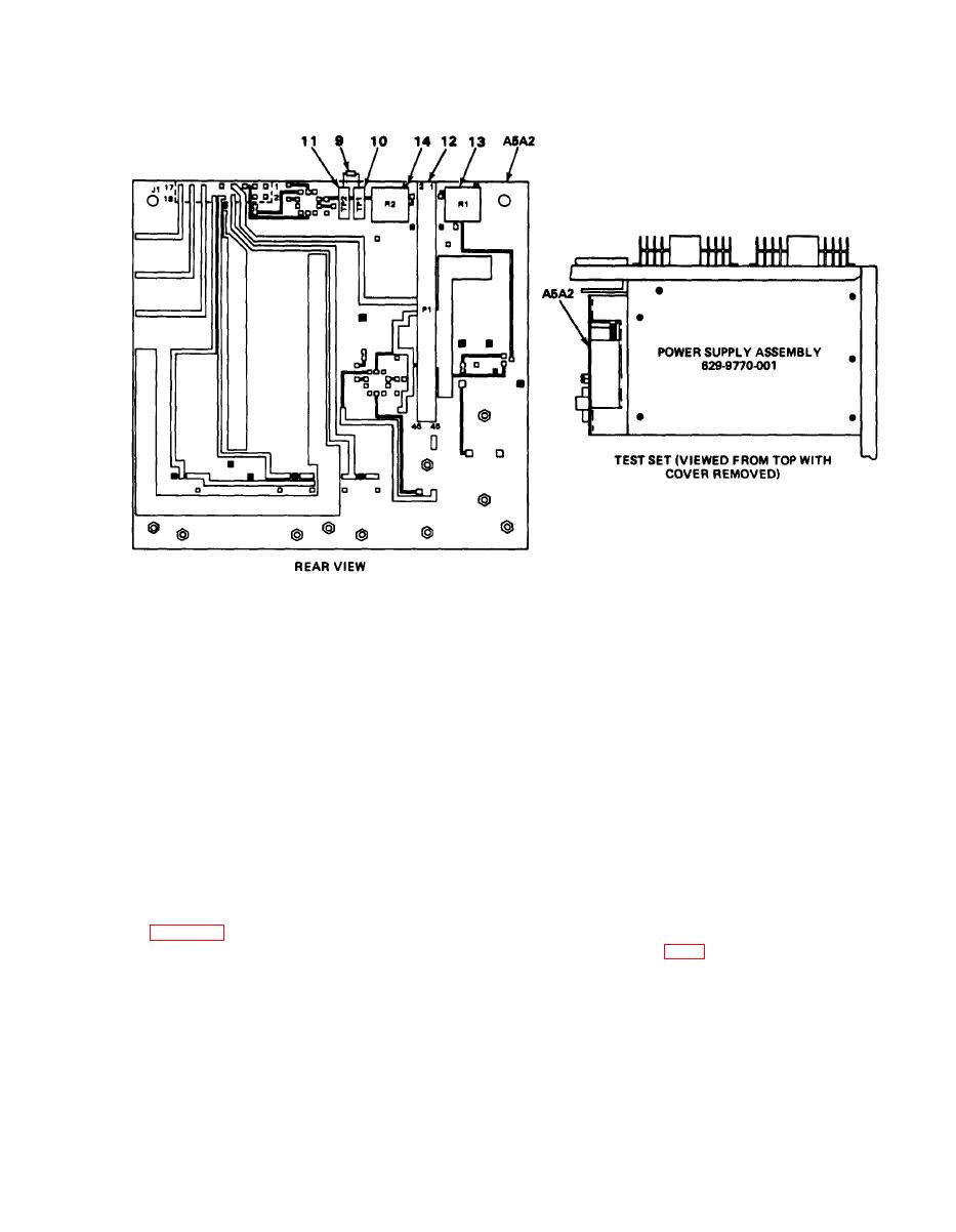
2-22. POWER SUPPLY ALINEMENT. (CONT)
EL9LY032
7. Connect 100-ohm resistor (9) between A5A2TP1 (10) and TP2(11).
8. Connect digital voltmeter to A5A2P1 pin 29 (12).
9. Turn A5A2R1 (13) and A5A2R2 (14) fully counterclockwise.
Turn equipment on. Allow at least 30 minutes for warmup.
PROCEDURE
10.
Adjust A5A2R2 (14) until digital voltmeter indicates 6.4 0.1 vdc.
11.
Slowly adjust A5A2R1 (13) until digital voltmeter drops to less than 1.5 vdc.
12.
Turn test set power off.
13.
Remove 100-ohm resistor (9) from TP1 (10) and TP2(11).
14.
Turn test set power on.
15.
Adjust A5A2R2 (14) until digital voltmeter indicates 5.00 0.05 vdc.
16.
Turn test set power off.
17.
Disconnect digital voltmeter from test set.
18.
Reconnect wiring harness connector P1 to matching A5A2 module pins. (See illustration,
19.
Connect digital voltmeter to connector pin A2A3J1-8 on assembly A2 (FO-6).
20.
Turn test set power on.
21.
Adjust A5A2R2 (14) until voltmeter indicates 5.00 0.5 vdc.
22.
Turn test set off and disconnect meter from A2A3J-8.
|
|
Privacy Statement - Press Release - Copyright Information. - Contact Us |