 |
|||
|
|
|||
|
Page Title:
AM MODULATION PERFORMANCE TEST. |
|
||
| ||||||||||
|
|
 TM 11-6625-2975-40
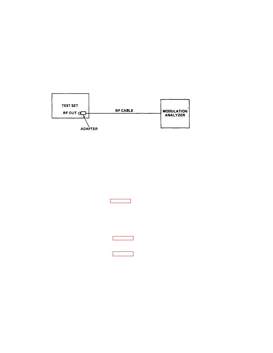
TEST EQUIPMENT REQUIRED: Adapter,N plug-to-BNC jack
Modulation Analyzer HP 8901
RF Cable RG-58/U
EQUIPMENT SETUP: Connect test set to 115 vac power source.
Connect modulation analyzer to test set as Indicated In the following diagram.
EL9LY021
Turn on equipment. Allow at least 30 minutes for warmup.
PROCEDURE
1.
Enter frequency 110.10 MHz into test set.
2.
90 Hz TONE SELECT key remains lit. Extinguish 150 Hz VAR TONE SELECT key.
3.
Press (to light) % MOD FUNCTIONICONTfiOL key. RDL/DDM/MOD display indicates 20.0
MOD (%).
4. Reduce RF LEVEL TO 6 dB mW.
5. Observe modulation analyzer. If modulation analyzer does not indicate between 19.95 and
20.5 percent AM, go to troubleshooting chart 2-1, sh 10.
6. Press and release STD key.
7. Enter frequency 113.00 MHz into test set.
8. 30 Hz VAR TONE SELECT key is lit. Extinguish 9960 FM TONE SELECT key.
9. Press (to light) % MOD FUNCTION/CONTROL key. RDL/DDM/MOD display will indicate 30.0
MOD (%).
10. Observe modulation analyzer. If modulation analyzer does not indicate between 29.25 and
30.75 percent AM, go to troubleshooting chart 2-1, sh 10.
11. Extinguish 30 Hz VAR TONE SELECT key. Press (to light) 9960 Hz TONE SELECT key.
12. Observe modulation analyzer. If modulation analyzer does not indicate between 29.50 and
30.50 percent AM, go to troubleshooting chart 2-1, sh 10.
13. Enter frequency 332.00 MHz into test set.
14. 90 Hz TONE SELECT key is lit. Extinguish 30 Hz VAR TONE SELECT key.
15. Press (to light) 70 MOD FUNCTION/CONTROL key. RDL/DDM/MOD display will indicate 40.0
MOD (%).
|
|
Privacy Statement - Press Release - Copyright Information. - Contact Us |