 |
|||
|
|
|||
|
|
|||
| ||||||||||
|
|
 TM 11-6625-2885-30/NAVAIR 16-35TS3614-2
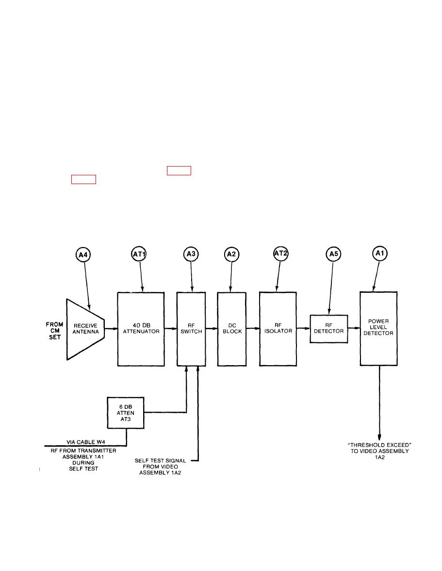
RECEIVER ASSEMBLY 1A3
AN/ALQ-136(V)1 system. The RF signals are then attenuated by attenuator (AT1)
and passed through RF Switch (A3), DC Block (A2), and RF Isolator (AT2). The
RF signals are detected by RF Detector (A5) and compared to a preset value in
Power Level Detector (Al). When the preset value is exceeded, a signal
(threshold exceed) is generated and sent to Video Assembly 1A2.
In self test, a self test signal from Video Assembly 1A2 operates RF Switch
(A3). RF signals are then supplied from Transmitter Assembly 1A1 through test
cable W4 and attenuator AT3 to RF Switch (A3). Self test RF then passes from
switch A3 through DC Block (AZ), RF Isolator (AT2), and RF Detector (A5) to the
power level detector. Figure FO-6 is the schematic for the receiver, and
Figure FO-7 is the schematic for the power level detector.
|
|
Privacy Statement - Press Release - Copyright Information. - Contact Us |
