 |
|||
|
|
|||
|
|
|||
| ||||||||||
|
|
 TM 11-6625-2885-30/NAVAIR 16-35TS3614-2
TRANSMITTER ASSEMBLY 1A1
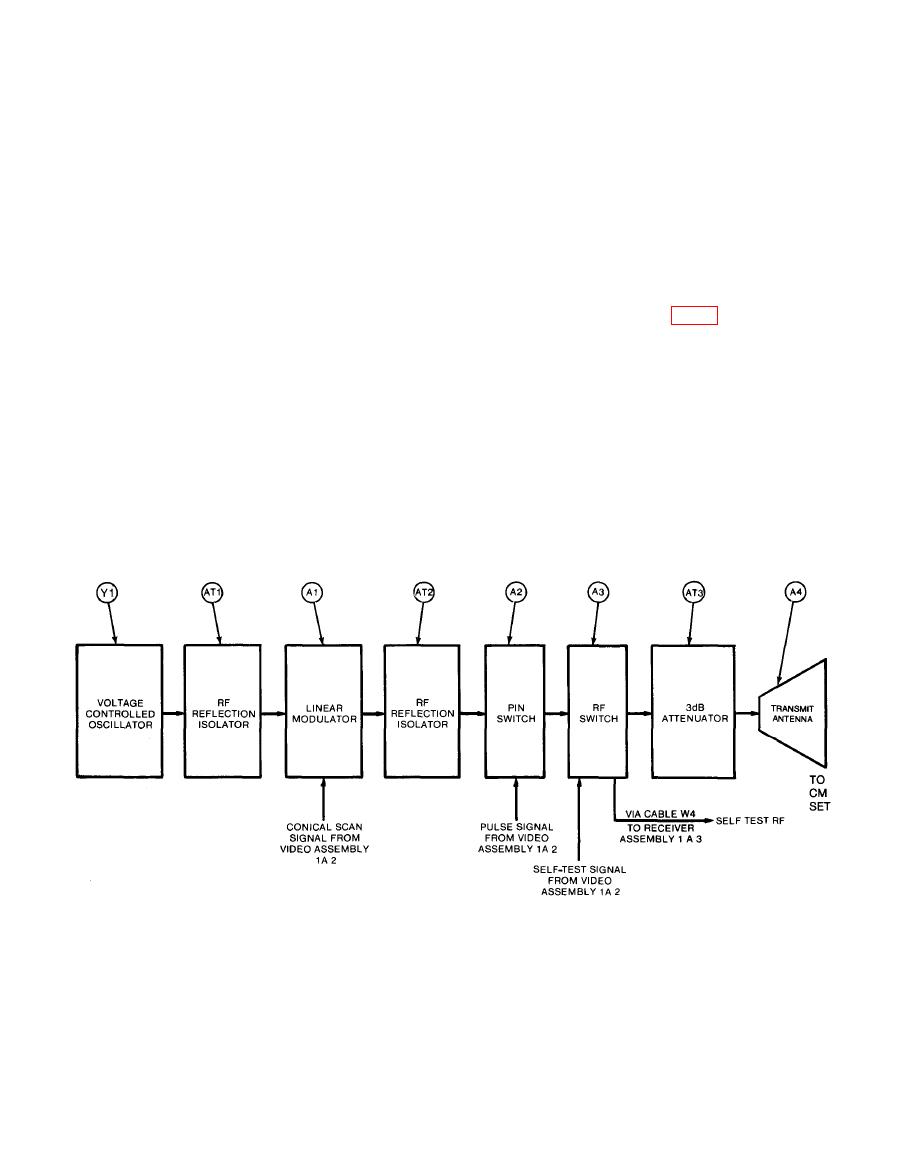
2-8. In Transmitter Assemblv 1A1. Oscillator (Y1) generates an RF carrier at
the output frequency. This RF carrier passes through RF reflection isolator
(AT1) to linear modulator (A1), which modulates the carrier with conical scan
(sine wave) signals from Video Assembly 1A2. The modulated RF signal then
passes through RF Reflection Isolator (AT2) to PIN Switch (A2), which applies
pulse modulation from Video Assembly 1A2. In normal operation, the modulated
RF signal is then supplied through RF Switch (A3) and Attenuator (AT3) to
Transmit Antenna (A4).
In self test, Video Assembly 1A2 operates RF Switch (A3). This sends the mod-
ulated RF signal to Receiver Assembly 1A3 through cable W4. Figure FO-5 shows
the transmitter schematic.
|
|
Privacy Statement - Press Release - Copyright Information. - Contact Us |
